Home Page Lesson
2 Lesson 3 Lesson 4 Lesson
5 Lesson 6 Lesson 7 Lesson
8 Lesson 9 Lesson
10 Lesson 11
FUNDAMENTALS - 1
BASIC PHYSICS THEORY
This is a simplified discussion of the basic Physics
which underlies our theory of Electricity and Magnetism.
LESSON 1
1.1 THE ELECTRIC CURRENT
Classical theory holds that Matter can be divided into smaller and yet smaller
particles until a point is reached where further division causes a change
in the properties of that matter. This smallest unchanged particle is called
a Molecule.
Most molecules can be sub-divided but often the resulting Matter has
properties which are unlike those of the parent molecules;
these smaller particles of different form are known as Atoms.
Any attempt to sub-divide atoms results in their destruction and so atoms represent
Nature's ultimate building-blocks. Atoms are known in more than 90 different
kinds and, because they are the fundamental building-blocks, they are known
as elemental atoms and the different kinds of Matter
which they form are called Elements.
Matter in which the molecules are formed by bonding together different atoms
is referred to as a Compound. (A mixture differs
in that it contains different kinds of molecules which are not bonded together
and so they can be separated from the mixture as Elements.)
Elemental atoms bond with each other to give
us the pure substances such as Copper, Oxygen and Iron (not Steel which is
a compound of Iron). Compounds of different atoms are represented by such things
as Water (Hydrogen and Oxygen), Salt (Sodium and Chlorine) and ultimately Life
itself.
** Research into the nature of atoms gave rise to puzzling phenomena
which, under mathematical analysis, has led to the conclusion that the atoms
are themselves constructed from a large variety of very-small particles. For
our purpose here it is necessary to consider only the first stage of that analysis
which says that an atom contains a relatively-heavy Nucleus around
which is gathered a number of extremely-small Electrons. The
different Elemental Atoms owe their differing characteristics to the differing
numbers of electrons which they possess.
** It is found by experiment that, when electrons are placed together,
they actively repel each other; similarly when two nuclei are placed together
they too actively repel each other. However, when a nucleus and an electron
come together, they exert a powerful mutual attraction.
** This behaviour is explained in terms of two differing Electric
Charges which, by tradition, are labeled as positive (+)
and negative (-). Also by tradition the positive
charges are attributed to nuclei and the negative charges to electrons.
The argument then put forward is that two like charges (either two nuclei
or two electrons) mutually repel while two unlike charges (a nucleus and
an electron) mutually attract.
** A complete atom does not show a tendency either to attract or to
repel other atoms and so it must be concluded that overall they have zero electric
charge; this must indicate that there are an equal number of positive
and negative charges. To cope with this the heavy nucleus is sub-divided into
an appropriate number of Protons each of which carries
a unit positive charge; there is one proton to match each electron in every
atom.
Some electrons, held only weekly by their parent atom, can be dislodged; atoms
which lose electrons in this manner are left with positively-charged holes which
then exert a mutually-attracting force with any passing electron and so tend
to re-fill themselves. However, if the disturbing force is more powerful
than the recovery force of the atom, the dislodged electrons can drift away
and form a moving stream of "free" electrons which is believed
to constitute what we know as an Electric Current.
1.2 THE WATER ANALOGY
Just before 1800 interest began in a new Science called Galvanism
following the experiments of an Italian scientist named Galvani. In an
effort to make sense of the phenomena they were uncovering the learned men
of the day drew an analogy between the electrical effects they were discovering
and the water systems which they used and understood.
They knew that a water pump, by raising a pressure
of water, could drive a current of water through
a system of pipes. Similarly they imagined that their generators of electricity
behaved as an electricity pump, that they raised an electrical pressure which
then drove a current of electricity through a system
of electrically-conducting paths.
To a large extent that analogy is still accepted
today. As described above a generator of electricity is considered to
"pump" electrons continuously from a point of low-potential to
a point of high-potential (it creates an electrical
pressure); the point from which negatively-charged electrons are removed
is left with a residual positive charge while the point where the electrons
are dumped acquires a surplus of negative charge.
A circuit Designer provides a suitable conducting
path external to the generator through which the surplus electrons, piled-up
on the negative terminal stream back to the positive terminal where they are
gathered up and pumped again and again to the negative terminal This is why
there must always be a complete circuit before electricity will flow.
This analogy with a water system is useful
in explaining the ideas behind electrical theory and it is used often in the
following text.
1.3 ELECTRIC SOURCES
In practice it is not that easy to set electrons
drifting and, as a general principle, they have to be pulled from one direction
with a positive charge and pushed from the opposite direction with a negative
charge. The prime-mover in such an operation is known as a Generator of
which the two major types are the Chemical Cell and
the Mechanical Generator.
1.3.1 The Chemical Cell
** There are many designs of Cell and they have many intended purposes
but their general requirements are a mixture of chemicals in which are immersed
two plates called Electrodes. These are usually made
from different materials; see Fig.1. The different
materials of the electrodes react differently with the chemical mix and this
results in electrons being stripped from one electrode with an equal number
deposited on the other.
** The basic construction of electric cells is shown in Fig.
1. The electrode which loses electrons :is left with a non-neutralised
positive charge while the other, with too many electrons, acquires a negative
charge.
Experimenters quickly discover also that it
is necessary to mechanically-restrain the electrodes because the unlike charges
which they carry set up a mutually-attractive force which pulls the electrodes
together.
 |
** As already discussed the holes on a positively-charged
electrode will attract electrons while the surplus electrons on a negatively-charged
electrode will repel electrons; it follows therefore that, as the
electrodes acquire their charges, so those charges try to force electrons
back across the cell.
** Ultimately a state of equilibrium is reached where
the chemical action of the Cell is exactly balanced by the reverse
action of the charged electrodes and the electro-chemical activity
of the Cell is halted.
** Between the two electrodes there now exists a distinct
difference in their state of charge and this is referred to as a potential
difference but is usually referred to simply as a p.d. The
essential character of a p.d. is that it is called into being by a
transfer of electrons (a transfer of charge); a p.d. can be generated
across other electrical components where it can be used as a "secondary
generator" to start another transfer of charge - another electric
current.
** A potential difference is an electric force which is equivalent
to pressure in the water analogy and it is measured in units named volts in
honour of the Italian scientist Volta.
An electric current, which flows under
the influence of electric pressure (volts), is measured in terms of
the number of electrons which drift past a given point in a period
of one second; of course we cannot count them and current has to be
assessed through the various effects which it produces.
(The standard torch battery delivers approx. 1.2
to 1.5 volts: this experimental cell delivers 0.6 volts approx.) |
** The number of electrons involved is measured in coulombs (after
Coulomb) which therefore are units of quantity (charge or no. of electrons);
the flow-rate in coulombs-per-second (no.of electrons per second) indicates
the strength of the current and this rate is expressed as amps. Properly
the unit of current-flow is the ampère named
after the French scientist Ampère but it is invariably shortened to
the more convenient amp.
1.3.2 Work and Power
To deliver water from a reservoir positioned
at some height above the delivery point requires a pipe; at the lower
end of that pipe there is a pressure caused by the weight of the water; this
is measured in terms of the height of the water-surface above the delivery
point and is known as the Head of Water.
The pipe allows water to be lowered from the
reservoir or, given a pump that can more than oppose the pressure, it allows
water to be raised to the reservoir. We have all moved objects either horizontally
over the ground or vertically and we complain that we have had to work;
fuel/food consumed in doing that work manifests itself as heat and we have
to take steps to cool down again or suffer heat-stroke. The faster the rate
at which we work so the hotter we get.
In such a mechanical world work is measured
by multiplying the weight that is moved by the distance through which it is
moved and the result can be expressed in units such as foot-pounds or centimetre-grams.
In the water system referred to above there
is a choice in that a small-diameter pipe can be used to deliver a given quantity
of water over a long period or a larger diameter pipe can be used to deliver
the same amount in an instant deluge. Should you be sprayed by the smaller
pipe you may get wet but otherwise would be unharmed; a similar acquaintance
with the larger pipe however could have serious consequences. The ability of
the large pipe to cause damage is described by saying that it delivers a powerful jet
of water.
** Because the larger pipe works (delivers water) at the greater rate we
say that it is a system of greater Power. Power
expresses the rate at which work is done and is measured
here by multiplying the pressure by the amount of water delivered per second. (Note
that a river delivers (at low pressure) - and therefore in innocuous fashion
- much more water-per-second than a dangerous water hose.)
** To transfer this concept into the electrical world:
The amount of water delivered becomes the amount (the number)of
electrons moved (or the amount of charge which has been transferred); the
amount is measured in coulombs.
The rate at which the water is delivered becomes the rate at which electrons
drift and is measured in amps.
The head of water (the height through which the water falls) becomes the electrical
pressure or p.d. and is measured in volts.
The power of the water jet becomes the electrical power dissipated as heat
and is measured as before by multiplying pressure (volts) by rate (amps).
** The unit of power in an electrical circuit (volts x amps) is the watt named
in honour of the Engineer James Watt.
Power appears as heat in the component through which the current flows and
across which the voltage is developed and, of course, it causes a rise in the
temperature of that component. This temperature rise continues until the rate
at which heat is lost to the environment equals the rate at which heat is being
generated. The heating effect is inescapable and so components must be designed
so that they dissipate enough heat to keep the temperature within designed
limits; care must be exercised in placing hot components.
When, as in Fig.2,
an electrical path is connected between the terminals of a cell it is to be
expected that an electric current will flow as electrons are propelled from
the overcrowded negative terminal to the positive terminal. The process
deserves a closer look however because it conceals a very important principle.
As soon as the external connection is made
the electrons begin to slide, snakes-and-ladders fashion, down the potential
gradient from the negative to the positive terminal. In
doing so they upset the equilibrium that had been established between the charged
electrodes and the chemical mix and so the chemical generation of electric-charge
re-commences. This causes the escaped electrons to be gathered up again and
replaced on the negative terminal to go around the circuit again and again; the
cell is seen to be acting as a pump as envisaged when drawing the water analogy.
** The important action, which applies to every generator, is the destruction
of the equilibrium; while that remains intact the chemical action is
halted and the call cannot maintain a current flow. It is a fact of Life
that, when any generator is called on to supply current, its terminal-voltage
falls. The greater the demand for current so the greater must be that
fall; the greater must be the failure to achieve that equilibrium.
This natural phenomenon is an annoying inconvenience
for the designer-engineer who, to calculate the current which will flow in
the circuit he designs, needs to know the terminal voltage; the problem
is that he cannot know the terminal voltage until the value of the current
is known! There is a simple and elegant solution to this problem which
involves thinking in terms of "perfect" theoretical generators which
could not possibly have a practical existence; the matter is dealt with
under 1.15: Internal Resistance.
Fig.2 Cell with an External Path |
** From the above description it is clear that
current which is supplied by a chemical cell flows always in the same
direction namely from the negative to the positive terminal. Confusion
arises because, in early theorising, it was decided arbitrarily that
current would be taken as flowing from positive to negative. Enshrined
in many of the classical "Laws", and still to be found in
old textbooks, the convention survives and so it is important, where
confusion can arise, to state which convention is being used. It is
customary to refer to old-fashioned pos-to-neg flow as classical current
and to the now-accepted neg-to-pos flow either as electron-flow or
as electron current.
Current does not always flow in this
one-way fashion and so, as described here, it is called direct current
or simply dc. Reference is often made to a
"dc voltage"; this seldom causes confusion but
it is best avoided by using the correct term direct voltage.
The word battery is commonly used
wrongly also; it is a contraction of "battery of cells" and
implies a package which contains more than one cell. A
1.4-volt torch battery should be referred to as a cell; a
(nominal) 9-volt battery contains six such cells. |
1.3.4 Majority-carriers & Minority-carriers
The discussion above proposes that an electric
current is in fact a flow of "free" electrons. When dealing
with transistors and other semiconductor devices there is a great deal of talk
about n-type and p-type semiconductors and about majority and minority carriers.
The meaning of these terms is not particularly important for the RAE but, for
those who wish to know, the following explains the basic theory.
The basis of most semiconductor devices today
is the Element Silicon. However pure Silicon does not conduct an electric
current and it has to be contaminated or doped. Some
doping materials increase the number of free electrons (carriers) which are
available to create an electric current and the result is known as semiconducting
material with majority carriers ; others cause a decrease in the number
of free electrons and these form semiconducting material with minority carriers.
But how can a flow of electrons take place
in a material which is deficient in free electrons ? Imagine a pea-shooter
which is filled with peas ; if an extra pea is pushed into the
left-hand end of the tube a pea is expelled from the other end as all the peas
move along the tube from left to right. This is likened to the action
in a majority carrier.
Now consider the same pea-shooter filled with
peas but, instead of pushing-in one extra pea, a pea is sucked-out from the
right-hand end so leaving an empty space or "hole". Under
the force of suction the next pea in line jumps from position 2 into the end
position once occupied by the extracted pea so causing an impression that the
hole has jumped to the left from position 1 to position 2. The pea in position
3 jumps into the hole vacated by pea no.2 thus causing the hole to move apparently
one more step to the left. In this manner the peas all move to
the right as before but the hole appears to move in the opposite direction
until a space is created at the left-hand end of the tube for the injection
of another pea. This is the mechanism suggested for current-flow by minority
carriers.
The two types of material produce transistor devices which have different
properties.
END OF LESSON 1
* * * * * * *
* * * * *
QUESTIONS
1. The very smallest particle of Matter is the Atom. How is this
related to the Molecule?
2. What are the constituent particles of the Atom as far as Radio Theory is
concerned? How do we allocate electric charges to them?
3. Although atoms bond together chemically to form large quantities of either
Elements or Compounds they do not show any electrical attraction (or repulsion)
to each other. How do we account for this electrical
neutrality?
4. What does Standard Theory propose as an explanation of the flow of electric
current? What is thought to be the action of a Cell by which it causes
current to flow around an electrically-conducting path?
5. In constructing electric cells how do we ensure that the two electrodes
offer different potentials?
6. Unless it is provided with a complete electrically-conducting path between
the electrodes a cell ceases to produce current; what sets-up the equilibrium
that makes current-production impossible?
7. What are the Units that are used to express the magnitude of::
(a) current-flow
(b) electrical pressure or p.d.
(c) power that is dissipated when current is driven through an electrically-conducting
path?
Back to Top of Page
LESSON 2
1.3.5 Mechanical Generators
** These generators too come in many different forms and serve
a variety of purposes but they have a common principle of operation. Mostly
they are rotary machines which combine a rotary mechanical force (a torque) with
a magnetic force and, in some manner which is well documented but totally unexplained,
cause a flow of electric current.
The traditional argument is that an electric current flows
under the influence of a p.d. and indeed this is the explanation usually accepted
for mechanical generators whose action is thought to generate a voltage. However,
as electrical theory is developed, problems can arise if this line of thought
is taken too literally. In as much as we are unable to explain the operation
of these machines there is justification for accepting the reverse order namely
that the machine causes current to flow and that this current transfers electrons
from one of its terminals to the other. To accept that positive and negative
potentials arise in this manner does not affect the above argument in the creation
of equilibrium conditions and so does not invalidate the explanation of the
fall in terminal voltage when current is permitted to flow.
** Whatever the truth may be it is usual to regard all generators
as possessing an internal force that encourages the migration of electrons; this
motivating force is called the electromotive force of
the generator and is invariably used in its contracted form emf. The
emf represents the voltage that appears between the terminals of a generator
when the current-flow is zero; i.e. it is the equilibrium voltage referred
to above. The lesser voltage which results when current is flowing is usually
called the terminal voltage.
** The difference between emf and terminal-voltage is important
particularly in practical calculations but the subject is dealt with in greater
detail under 1.15: Internal Resistance.
** There are occasions when the concept of emf is abandoned and
a generator is considered as delivering a current;
this matter too is dealt with under Internal Resistance.
** Because of the construction of mechanical generators and
their mode of operation they do not produce direct current but one which changes
cyclically in both strength and direction. The output from these machines is
called alternating current but it is usually referred
to by the initials ac; again it is not uncommon to
see reference to an "ac voltage" but the correct term is alternating
voltage. Machines which produce ac are called alternators
There is a rotary machine called a dynamo which
allegedly produces dc; in fact it is an alternator but has a built-in
rotary switch (a commutator) that, literally, reverses
the connections each time the current reverses direction. The "alternators" fitted
to modern cars are in fact alternators but they have built-in semiconductor devices
(see below) which imitate the action of the dynamo's rotary switch.
** In general it is easier and cheaper to generate in ac form than
in dc and, where direct current is required, a means must be provided to convert
between the two forms. This is dealt with fully in Part 5: Power
Suppliers. It is sufficient to note here that conversion
from ac to dc is a process known as rectification and
the devices used are called rectifiers. Conversion
from dc to ac is termed inversion and is achieved
in equipment known as an inverter.
1.3.6 Polarity
** This term is used to describe the direction in which an emf or p.d.
acts. For example it might be said that the polarity is such that Terminal-A
is more positive than Terminal-B. At the output terminals of an alternator
the polarity constantly reverses. Perhaps from this has sprung
the word pole which is used to indicate a point of
concentration; e.g. the terminals of a cell or a generator
can be described as its positive and negative poles; magnets, including
the Earth, have North and South poles.
1.4 CONDUCTORS AND INSULATORS
** The discussion of electron-drift began with the words: "… Some
electrons, held only weakly by their parent atom …" . There
are of course atoms which hold on very tightly to all their electrons and
consequently it is difficult to cause electron drift. Materials in
which electrons are not easily dislodged and which therefore do not willingly
conduct an electric current are called either non-conductors or insulators.
** Materials in which "free" electrons are easily dislodged
are called conductors and, usually, they are also
good conductors of heat. Most good conductors are metals but a notable
exception is the element Carbon; this appears in many forms and is a
most useful material in electrical engineering.
** None of the insulating materials are perfect in their action and
they all allow passage to small leakage currents. Leakages
tend to remain small even when the applied voltage is increased considerably
but, as the leakage current increases, so too does the amount of heat generated. Because
most insulators are poor conductors of heat excess leakage can cause a rapid
local rise in temperature and so insulating materials tend to fail suddenly
and self-destruct.
** There is a class of materials midway between conductors and insulators
which are known as semiconductors; these
can be switched electrically between states of conduction and non-conduction
without suffering damage and they form the basis of transistor and chip technology.
1.5 RESISTANCE AND RESISTORS
The argument above has been that some kind of electromotive
force is required to dislodge free electrons if an electric current is to be
set in motion. Without that emf any current-flow in existence ceases and so
the only logical conclusion is that the material fights back; it
does not approve of its electrons being harried and moved-on . In fact such
action has been mooted already by pointing out that a dislodged electron leaves
behind it a positively-charged hole with a distinct come-hither to any nearby
electron.
** In short, even though a material may be classed as a conductor,
it resists a flow of electric current. This action is referred to as the material's resistance;
it is measured in ohms in honour of the German physicist
Ohm.
** For most materials resistance is a property which is determined
only by the length and cross-section area of the conducting path. Considered
as a standard unit, such as a 1-inch cube, the resistance does not change. In
terms of a standard unit however each material has its own specific
resistance. Metals such as Copper and Silver have very
low resistances but glass offers a very high resistance.
** Some specially-made materials have resistances which vary according
to some other parameter; for example; their resistance may either rise
or fall when they get hot. See also under 1.12.1 Ohms Law.
** In one sense resistance is a nuisance to the electrical engineer
and yet, without resistance, it would not be possible to control a flow of
current. The behaviour of electrical and electronic circuits depends
on the values of resistance that are present in different parts of those circuits. Components
are manufactured therefore to provide known specified amounts of resistance
and these are known as Resistors.
** Apart from possessing different values in ohms resistors are manufactured
in different physical sizes; large components provide a larger surface
area through which to lose heat and so they can handle greater powers than
small components. Modern materials can operate at higher temperatures
than the older carbon-type resistors and so the physical sizes have tended
to decrease; additionally in the low-power circuits of modern semiconductors
power-ratings tend to be much lower than in valve circuits. However it
is necessary to be aware of the heat which resistors may generate and to place
them accordingly in a piece of equipment.
** Resistors are manufactured also in forms which enable their value
to be adjusted. One such has been mentioned above which is made from material
which is temperature sensitive. Other types can be varied by mechanical adjustment,
by varying the voltage applied to them, by illuminating them with light or
some other radiation, by exerting on them a mechanical pressure.
** Valves and transistors in their various functions perform as variable
resistors; see Part 3: Electronic Amplifiers.
In some branches of engineering resistance
itself is the end product. There can be few homes which do not possess a physically-large
resistor designed deliberately to get hot without self-destruction and known
variously as an
electric fire, a kettle element, an immersion heater, a
light bulb … ?
1.6 ELECTROMAGNETISM
** Under 1.3.4 Mechanical Generators it
was stated that an emf drives an electric current through a conducting material
but there are also other effects of applying an emf. Fig.
3shows a length of conductor connected across a cell via a switch. It
was probably discovered by accident but, when a small compass needle is placed
beside the conductor, the needle is seen to move whenever the switch is closed
and to return to its original position when the switch is opened once more.
** A compass needle possesses the property of magnetism which
means that it exerts a magnetic force on certain
materials the most common of which is the element Iron. The exact nature
and origin of the force are not known.
A compass needle has at one end a North
Pole and at the other end a South Pole; the
North Pole is named because it points toward the North Pole of the Earth
and this indicates that the Earth too is a magnet. There is a natural
rule that unlike forces attract while like forces mutually repel (as described
with electric charges) and so the North Pole of a compass needle should
not point to the North Pole of the Earth.
The confusion arises because the Earth's
"North Pole" should properly be called the "North Geographic
Pole" and the north pole of the compass needle is properly called the
"North-seeking Pole"; the Earth's north magnetic pole is
close to its South Geographic pole.
** To return to Fig. 3 that the compass needle
moves when the switch is closed, shows that an electric current calls into
being a magnetic force and that this dies away again when the current ceases
to flow. A magnetic force which is sustained by an electric current is
called an electromagnetic force;
apart from its dependence on a current such a force is indistinguishable from
the permanent magnetic force exerted by magnets such
as the Earth or a compass needle. See also under 1.8: Fields of
Force and under 1.9: Induction, Inductance and Inductors.
1.7 CAPACITANCE and CAPACITORS
1.7.1 Electron-flow in a Capacitor
** Capacitance is the ability to store
electric charge; sometimes it is a desirable property and sometimes it
is a downright disadvantage. A component manufactured to provide a known or
controllable amount of storage capacity is called a capacitor.
** A capacitor consists of two parallel plates made of conducting material
which are separated by an insulating material referred to as the dielectric;
sometimes the dielectric is just air. Such an arrangement is shown in Fig.
4 where it is connected to an electric cell.
** As chemical action removes electrons from the positive plate of
the cell so electrons belonging to the attached capacitor plate are attracted
and, for a short period, an electric current flows in the connecting wire.
Equally, as the cell deposits electrons on its negative plate, so they are
repelled and move to the other plate of the capacitor; for a similar short
period a similar current flows in this connecting wire also.
Fig. 4 Charging a Capacitor
** The surplus of electrons accumulated on the negative plate of the
capacitor cannot transfer to the positive plate and so return to the cell because
they lack a conducting path and so +ve and -ve charges build-up on the capacitor
plates. When the p d. between the capacitor plates equals the p.d. between
the cell terminals then electrons can no longer be forced either into or out-of
the capacitor and so the action ceases. This process is referred to as charging
the capacitor.
** In the equilibrium condition, with the current in each connecting
wire at zero, the capacitor is said to be fully-charged but
it is a purely relative term. Should a larger-voltage battery be substituted
for the single cell shown then the equilibrium would be destroyed and so the
charging process must recommence.
An instrument built to record the passage of
an electric current (an amp meter) is known as an ammeter;
such an instrument set in either of the connecting wires would, during the
charging process, record the passage of a direct current which started at some
value and decayed to zero.
** The real usefulness of a capacitor is revealed however when the
cell or battery is removed and an alternator substituted. While the capacitor
does its best to acquire a charge it is continually frustrated because the
alternator constantly reverses the polarity; electrons are first pushed
into the capacitor, then withdrawn only to be pushed back again and again with
each successive cycle of the alternator. The ammeter perceives only a
stream of electrons which moves first one way and then the other and so it
dutifully records the passage of an alternating current. Note that electrons
do not circulate as with a d.c.
** A capacitor therefore has a very-important property in that it blocks
the passage of dc (after an initial charging current) but apparently permits
free passage to ac.
The oppositely-charged plates of a capacitor exhibit a
strong mutual attraction as do the plates of a cell;
an instrument for measuring voltage can be made by allowing one plate to move
against the return-action of a spring.
1.7.2 Dimensions of a Capacitor
When the plates of a capacitor are allowed
to approach each other the opposing charges which they carry tend more and
more to cancel; the resulting destruction of equilibrium means that the
cell will re-commence charging the capacitor. The effect of reducing the gap
between the plates of a capacitor therefore is that it can accept a greater
charge; i.e. reducing the gap increases the capacitance.
More electrons can be stored on the surface
of a large plate than is possible on a small plate and so capacitance (the
ability to store charge) is dependent also on the surface area of the plates; the
greater that area the greater is the capacitance. The shape of the plates is
not relevant.
That capacitance depends only on the area of
the plates and on their separation means that capacitance can exist between
any surfaces which have sufficient conduction to allow electrons to spread
over their total area.
** Capacitance is measured in units named after Faraday and called Farads; however
a capacitor that offers but a single Farad is about the size of a normal room
and practical capacitors are measured in microfarads which
are one-millionth of a Farad (mathematically 10-6 Farads).
The practical range of capacitors goes down yet again by a million to what
were once called micro-microfarads but which are now named picofarads (10-12 Farads); pF's
are normally referred to as "puffs".
1.7.3 Stray Capacitance
** It was stated in the previous Section that capacitance exists between
any conducting surfaces; such all-pervading and unavoidable capacitances
are referred to as stray capacitances or simply as strays.
The alternating currents which these allow to leak in all directions are a
curse. Experience and careful design can keep their values to a few picofarads
and, in general, they do not become a serious nuisance until the frequency
range approaches a few MHz.
** There are four ways of dealing with stray capacitance once it has
been reduced to a minimum:
(a) make use of it by incorporating it into the
design (see Distributed Amplifiers)
(b) arrange the circuitry so that currents introduced
through stray couplings cancel; see under 1.10: Transformers,
(c) screening (shielding) techniques which are described
in the next Section
(d) deliberately introduce a similar current which
cancels the flow through the stray coupling;
this technique is referred to as neutralising and
is described in Part 4.2: Transmitters.
1.7.4 Static Electricity
In Lesson-1 it was proposed that an electric
current consisted of a drift of free electrons which are propelled away from
a negatively-charged electrode (or terminal) toward one that is positively-charged
. In this Lesson it was proposed also that such a drift of electrons
could flow "into" a capacitor ; i.e.
that free electrons would accumulate on one plate of the capacitor and that
a dearth of electrons (a collection of "holes") would accumulate
on the other plate.
When the source of e.m.f. is disconnected from
such a charged capacitor then clearly the electrons must tend to flow from
the negatively-charged plate back to the positively-charged plate but this
is not possible because they lack a conducting path along which to create that
flow.
The result of such actions is a capacitor which
has:
(a) a surplus of electrons on one plate
(b) a dearth of electrons on the other plate
(c) an electric field in existence between the two plates (there is an electric
force between the plates)
(d) a mechanic force which tends to pull the two plates together.
Clearly the capacitor is involved with electricity
but , even though the electrons are free from their parent atoms, they are
not in the form defined in that they are not drifting.
A stream of drifting electrons are mobile electrons
or dynamic electrons and the electricity
which is ascribed to their action can be described as dynamic electricity. Electrons
which are sitting on one plate of a capacitor - electrons which are being stored
in a capacitor - form a standing/stationary charge and are referred to as static
electricity.
Perhaps the most noticeable effect of static
electricity is the mechanic force which it manifests. A useful party trick
to amuse children while the jelly and cream is awaited is to rub a balloon
on a woolen Jersey or some suit materials and
then "stick" it to the ceiling. Provided the room is dry
then friction between the cloth and balloon will transfer electrons; one
of them acquires a positive charge and the other a negative charge. As the balloon
approaches the (dry) ceiling so it induces an opposite charge on the surface
and the mechanic force between the two charges is capable of supporting the weight
of the balloon.
Why the emphasis on the word
"dry" ? Water is not a very good conductor of electricity
but it is sufficiently good to allow small static charges to leak away. Hence,
in a damp atmosphere, the balloon's surface is slightly moistened and any
charge induced on the balloon may well return to the cloth as fast as it is
formed. Alternatively it may leak away via the performer's hand and
finally it must leak away across the ceiling so that the balloon remains in
place for a disappointingly short period.
In a warm and dry room friction effects between clothing,
furnishings, shoes, carpets and the air as we move about generate static charges
of surprisingly large values; they can be as high as 1,500 volts. Such
high voltages can be lethal - indeed under the right circumstances 50-volts
can kill - but normally we are totally unaware of these static charges. Most
people however have experienced the crackle as they remove clothing or comb
their hair which is generally described as "static"?
The capacitor which stores these static charges is
in fact our own bodies. Perhaps, to be more accurate, it is the capacitance
between our bodies and surrounding objects. This stray capacitance has a very
small value and so it requires but few electrons to charge it to high values.
The transfer of such small amounts of charge represents but a very-small electric
current and so we remain unaware of their presence - mostly !
One area in which these small charge-transfers
become important even to the point of disaster is when handling semiconductor
devices of the type described in later Lessons as CMOS (complementary
metal oxide semiconductor). These employ insulating layers of glass a few nanometres
thick (virtually a few molecules in thickness) and this insulation is easily
punctured by the static discharge. CMOS devices are destroyed simply by grasping
them in the hand unless precautions are taken to discharge the static electricity. Briefly
this involves ensuring that the human operator, tools, bench surface, CMOS
devices and the intended destination board are all at the same potential (most
conveniently Earth potential).
It is a dangerous practice however to connect
yourself to Earth because an inadvertent contact with a point of high-potential
could result in electrocution. So-called anti-static precautions involve connecting
everything to earth via a high-resistance which, while allowing static charges
to leak away, limits accidental currents to safe values.
Why do static charges produce visible flashes
and audible crackles when clothing is removed or a comb is passed through the
hair? The ability of a capacitor to store charge (its capacitance) is proportional
to the area of its plates . As those plates are moved closer together, so the
opposite charges tend to cancel and so the potential across that capacitor
decreases. By the same argument, as the plates are pulled apart, so the cancellation
effect is decreased and the potential across the capacitor increases.
In removing an item of clothing the gap between
cloth and body is increased and so the potential-difference between them is
increased ; the same effect occurs as a comb is withdrawn from the hair.
The p.d. rises until the dielectric - the air - breaks down (it dissociates
into positive arid negative ions) and the capacitor
is discharged by a spark. The spark causes the flash;
its supersonic passage
through the air generates a shock-wave which is the crackle. This
is traditional thunder-and-lightning on a microscopic scale.
These effects are most noticeable in homes
which use central-heating which causes air to be re-circulated and so rendered
dry. Where rooms are heated by open coal fires air is constantly vented through
a chimney so that fresh air is drawn in from outside; this raises the
humidity and lessens both the static charges that accumulate and unpleasant
bronchial effects.
Static electricity has some intriguing habits
but the subject is not examined for the R.A.E. Here are three curios
for the thoughtful:
1. Static charges always reside on the outer surface of a hollow body. Hence
it is possible to generate very large static voltages between two hollow metal
spheres, with thunderous discharges occurring between them, while machinery
and operators sit safely within.
2. An early capacitor, the Leyden Jar, consisted of two metal cups one inside
the other separated by a glass cup (or jar). Once charged the Jar can be disassembled
when tests will fail to reveal any sign of charge. Reassembled (with care)
the jar is found to be still charged
3. The handrails/bars on public transport vehicles are bound with cord where
passengers are likely to grip them. This is because friction between the moving
vehicle and the air charges the bodywork and provides a nasty surprise for
indignant would-be boarders. Similarly friction between clothing and leather/plastic
upholstery can charge passengers and drivers of motor cars who receive similar
unpleasant surprises when a foot touches the ground. To a large extent these
effects are now nullified by including an amount of graphite in the tyre composition
to provide a static leak.
In connection with (1) above it should be noted
that dangling leather straps and chains can do little to relieve the car-sickness
of passengers which is often attributed to these static charges. Such charges
- if present - will all be found on the outside surface of the car and so cannot
affect the passengers. A leak from car-body to ground will not discharge
the electric field between passenger and seat;
the cure is to change the upholstery material
END OF LESSON 2
* * * * * * *
* * * * *
QUESTIONS
1. Describe the basic difference in electron behaviour when
(a) a direct current flows through a resistor
(b) an alternating current flows through a capacitor.
In what particular way is a capacitor useful in electronic circuits
?
2. What is the basic difference between conductors, insulators and semi-conductors?
3. Insulators are given to sudden failure under excessive voltage; what
is the reason for the destruction which usually follows ?
4. Why are Resistors manufactured in different sizes ?
5. What is an electromagnetic force
6. Given two capacitors of different physical sizes and apparently of similar
construction which would you expect to exhibit the larger capacitance ? Explain
why.
7. What is the difference between a microfarad and
a "puff". Why do we not encounter capacitors that offer 1 Farad ?
8. What do you understand by the term stray capacitances ?
What is the principle that lies behind methods of eliminating their effects?
Back to Top of Page
LESSON 3
1.7.4 Time Constant
** To charge or to discharge a capacitor involves
either depositing electrons or removing electrons from it and this takes time.
The amount of time taken is determined by the current which flows because this
is a measure of the rate at which the electrons move. In turn the magnitude
of the current is determined by the resistance of the complete circuit.
 |
** Fig.4(A) shows
a capacitor connected via a resistor to a source of emf. At the instant
the emf is connected the capacitor is without charge and so its terminal
voltage is zero; this means that all the emf must appear across
the resistor and so the current which flows is determined only by the
values of the emf (E) and the resistance (R). The current I is given
by E/R(Ohm's Law).
For the capacitor/resistor arrangement
the time required at the initial rate is given by the product RC and
so, as a practical rule-of-thumb, a full charge or discharge takes
about 5RC seconds where R is in Ohms and C is in Farads. The quantity
RC is known as the circuit Time Constant and
it appears in any circuit where elapsed time is important. |
Back to Top of Page
1.7.5. Screening and Earthing
** Stray capacitive couplings (and the stray magnetic
couplings described under 1.9) which occur between a signal circuit and any
other piece of electrical equipment lead to the introduction of unwanted noise
signals and also to the creation of unwanted feedback loops (see under 1.11:
Amplification). Stray couplings are a fundamental part of Nature
and cannot be avoided but the signal currents which they allow to pass can
be diverted and rendered harmless.
** The great mass of the Earth can be regarded as an "electron
sink"; to pass unwanted electrons to the Earth or to acquire needed electrons
from the Earth does not change its potential in practical terms. Thus any conductor
which is connected electrically to the Earth is held at a constant potential.
Fig. 5 Mechanism of Screening Against Capacitive
Couplings
Screening consists of placing an earthed piece of metal (or metal mesh) between
the circuit to be protected and the source of interference. As shown
in Fig. 5 the stray coupling is divided into two
parts: (a) stray capacitance between the circuit and the screen and (b) stray
capacitance between the screen and the interfering source. Of itself the
screen provides little or no protection because currents from the interfering
source produce noise potentials on the screen and these potentials on the
screen then act as a noise-source in their own right to drive noise currents
through the circuit.
** Earthing the screen provides a path to earth for
noise currents which flow toward the signal circuit and for signal currents
which flow from it. Because the screen is now held at a constant potential
it can no longer act as a source to relay unwanted signals either into or out-of
the signal circuit.
** As a general precaution against stray capacitive couplings it is usual to
earth all signal circuits at some point thus ensuring that they carry only the
wanted signal potentials. When one of the circuit connections (one "leg")
is earthed, which means that signal information can be carried only on the other
leg, the circuit is said to be unbalanced; greater
protection from stray couplings is provided by balanced circuits which are described
under 1.10.3: Transformers.
** Where voltages in excess of 50 volts are present earthing
is employed as a matter of safety; equipment is enclosed either in insulated
cases or in metal cases and these last must be efficiently earthed if they
are to provide protection. Earth connections must not be removed even
when fault-finding or carrying-out maintenance routines unless the Operator
thoroughly understands the procedure; an unearthed metal case is coupled
by stray capacitance to the equipment inside and is only too willing to use
the unwary as a path to Earth.
1.7.6 Capacitive Reactance
** Although a capacitor does not provide a conducting
path between its two connecting wires those two connections always carry identical
currents. A capacitor thus provides a means of passing information in the form
of an alternating current between two points which are not electrically connected.
** The magnitude (the size)
of this current is a matter of the number of electrons which move into and
out of the capacitor and is determined therefore by (a) the magnitude of the
charging emf and (b) the capacitance (the storage capacity) of the capacitor.
The capacitance-value thus controls the magnitude of an alternating current
in the same manner as does a resistor.
** However there is a significant difference between the
alternating current which flows through a capacitor and that which flows through
a resistor. When a capacitor is fully charged (when the p.d. between its terminals
equals the charging emf) then the current falls to zero; i. e. the current
reaches a zero value when the p.d. reaches its maximum value.
** When a capacitor is in the middle of the operation
of discharging and then recharging in the opposite direction then the current
(the flow of electrons) is at its maximum value but, at that moment, the p.d.
across the capacitor is zero as it reverses polarity; i.e. the current reaches
a maximum value when the p.d. is zero.
** Where the ac applied to the capacitor is of sine-waveform
(see Part 7: Mathematics) the waveforms of
voltage and current are always displaced by 900 and are said to
be in quadrature; the effect of this is that
the power-flow (the product of voltage and current) is zero.
** In fact a capacitor can pass fairly-large currents
without getting warm while a resistor handling the same current could be destroyed
by the heat generated. For this reason ac which flows in a purely capacitive
circuit is often referred to as wattless current (power-less
current). To distinguish this wattless current-controlling action of
a capacitor from the power-dissipating action of a resistor it is given the
name Reactance but it is still measured in ohms; with
certain provisos it obeys Ohm's Law as does resistance.
Back to Top of Page
** Because a resistive current and a capacitive current have different phase relative
to the emf which drives them it is not possible to add the two values directly
and this is dealt with under 1.12: Resistance, Reactance and Impedance.
Similar behaviour is exhibited by inductors (see
under 1.9) but they produce a different quadrature relation between current
and voltage; to distinguish between them the two reactances are described by
the terms capacitive reactance and inductive
reactance.
1.8 FIELDS OF FORCE
In the domestic world a field
is an area (2-dimensions) characterised by grass although sometimes it may
be specified as (for example) "a field of corn" or "a cornfield".
In Physics a
field is a volume (3-dimensions namely length, breadth and height) throughout
which a force acts; it may be specified as an electric field (which
surrounds an electric charge or fills the space between electric charges), as
a magnetic field (which fills the space between and
around magnetic poles) or perhaps as a gravitation field (about
which we know very little).
Fields of force are represented graphically
by drawing lines-of-force; these have the following
purposes
(a) as with the contour lines which are drawn on maps
(they join points of equal height) lines-of-force join points of equal field-strength.
(b) at each point on a line-of-force the line
indicates the direction in which the force acts;
for example, an electron placed in an electric field will be attracted to
the positive pole and repelled by the negative pole and a line-of-force which
passes through that electron shows the direction of the resultant force (the
overall effect of these two forces when they act simultaneously).
(c) many lines-of-force drawn close together are
used to indicate a powerful field; this arises from their role as contour
lines in that they indicate the gradient of the field (the
way in which the field-strength changes over a distance) although it is seldom
that lines-of-force are allocated specific values.
** In an electric field the lines-of-force are defined
as showing the path that would be traveled by an isolated positive charge; it
follows therefore that electric force is deemed to act from the positive pole
to the negative pole.
** In a magnetic field the lines-of-force are defined
as showing the path that would be traveled by an isolated North Pole; in
fact we cannot achieve an isolated magnetic Pole but the concept gives rise
to the convention that magnetic force acts from the North Pole to the South
Pole. (An isolated Pole can be approximated by using a very-long bar or rod
magnet.)
Back to Top of Page
There is one very important difference between electric lines-of-force and
magnetic lines-of-force; see Fig. 6. Electric
forces always form open lines which terminate at one end on a positive pole
and at the other end on a negative pole; magnetic lines always form closed
loops which enter the magnetic source at the South Pole and continue through
the source to exit at the North Pole.
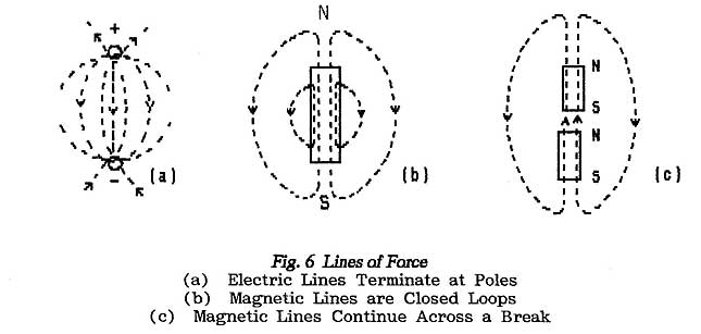
Any attempt to close an electric line-of-force into a loop, or any attempt
to open a magnetic loop, invariably decreases the magnitude of the force concerned.
Lines-of-force often show graphically the behaviour of a system. For
example Fig.7 shows in diagram (a) the electric field
between a negative pole and a positive pole while, in diagram (b), it shows
the field between two opposing positive poles. Diagram (a) is an ordered
pleasing pattern which is believably trying to contract while diagram (b) is
angular and the field patterns associated with each pole do appear to be pushing
against each other.
END OF LESSON 3
* * * * * * *
* * * * *
QUESTIONS
1. Potential difference (p.d.)
and electromotive force (emf) are both measured in volts. In what manner do
they differ?
2. What is the
property known as Reactance?
What do
you understand by the term "wattless current ?
3. Describe the
principle used in screening electrical circuits against intruding electric
fields.
4. Why is it
that resistive and reactive currents cannot be added directly using simple
arithmetic ?
5. What is an
electric field ?
6. What would
you deduce from a diagram that showed many lines of electric force close together
?
7. Why is it
that the terminal voltage of a generator must fall before the generator is
able to supply current ?
(Not needed
for R .A. E.)
8. What is the
difference between a battery and a cell ?
9. What is the
effect of connecting a conducting body to Earth ?
** Paragraphs marked with a double asterisk contain
material which is relevant to the RAE;
the remainder form a continuous explanation.
Back to Top of Page
LESSON 4
1.9 INDUCTION, INDUCTANCE AND INDUCTORS
1.9.1 Induction
** Under 1.6: Electromagnetism with reference
to Fig.3 it was explained that an electric current
generates a magnetic force. By exploring with a small compass needle
it can be established that the force acts in a circular path that surrounds,
and is concentric with, the conductor;
the magnetic field has the form of a cylinder pierced from end to end by the
conductor.
** The direction of the circular lines-of-force is related to the direction
of current-flow and this is the subject of a classical Law which states that,
when an Observer looks along the conductor in the direction of classical current-flow (i.e.
from positive to negative), then the magnetic force is always seen to act clockwise.
** Fig.8 shows a development of Fig.
3 in which a second conductor has been introduced close to
the first (or primary) conductor so that it lies within the magnetic field; this secondary
conductor is connected to an ammeter.
** It is an experimental fact which we cannot explain that, at the moment
the switch is closed, a current flows for a short period in the secondary conductor.
The secondary conductor then remains quiescent until the switch is opened when
again a current flows but this time in the opposite direction.
** That the secondary current-flow occurs whenever the primary current changes
its value can be demonstrated by substituting an alternator for the cell; the
primary current now changes value continuously and a constantly-changing current
of similar form is found to flow in the secondary conductor.
This somewhat mysterious transfer of electrical power from
the primary circuit to the secondary circuit is termed electro-magnetic
induction; it is the basis of an important component called
a transformer which is described in the next Section,
but the mechanism of the power-transfer is not known.
The current that is induced in the secondary
circuit is exactly the same as any other current and so it too brings into
being an attendant magnetic field; like the primary field this magnetic
field too surrounds both conductors and the two are said to be magnetically
coupled. A question arises as to whether the secondary
field aids or opposes the primary magnetic field?
To the ammeter the secondary conductor is a
generator and so there must be a fall in terminal voltage (the p.d. across
the ammeter) before current can flow and this fall must be dependent on the
strength of the current-flow; see under 1.3.3. Because
the secondary conductor derives it power from the primary by means of the magnetic
field such a fall in terminal voltage must be caused by a fall in the magnetic-field
strength. It follows that the magnetic field generated by the secondary
current must oppose the magnetic field generated by the primary current. Therefore,
as drawn in Fig. 8 the secondary current must flow
in a direction opposite to that of the primary current.
1.9.2 Self-Inductance
The above argument can be pursued however without
introducing the secondary conductor. When the primary current creates a magnetic
field the primary conductor itself is encompassed by that field; the primary
conductor therefore is in exactly the same situation as any secondary conductor.
Hence, when the primary current varies, an opposing secondary current should
appear in that primary conductor.
** Pursued to the limit this argument implies that any conductor
will carry a somewhat smaller ac than would be expected from its performance
with dc ?
By definition a direct current does not change
its direction of flow but it does often change its value especially when either
building from zero at switch-on or collapsing to zero at switch-off. If
the above arguments are valid it is to be expected that, even with dc, these
switch-on and switch-off periods are modified by the inter-action between a
conductor and its surrounding primary magnetic field.
** In practice all these effects are observed; in any given conductor,
for a given emf, the value of alternating current is less than that of direct
current. Because of this reduced-current effect it takes an appreciable
period of time for current to reach its final value at switch-on and to fall
to zero after switch-off.
** This phenomenon is given the name Inductance. It
is not difficult to believe that inductance can be a nuisance but, as described
in a later Lesson, it can also be of use and so components are manufactured
to provide a specified amount of inductance. These are called Inductors and
the amount of inductance provided is measured in units called Henrys (in
honour of Henry); note the spelling.
**The reduced value of alternating currents with respect to direct
currents is interpreted as an increase in resistance and, quite reasonably,
it is measured in ohms. However, as with capacitors, it is found that the alternating
current does not vary exactly in time with the applied emf and so the apparent "extra
resistance" of an inductor is referred to as its inductive
reactance (see also under 1.7.5: Capacitive Reactance).
** Again, because of the quadrature relation between current and voltage,
an inductor draws a wattless current and provides an efficient means of reducing
a
current-flow. In this application inductors are less efficient than capacitors
but they are often used where it is required to preserve a dc-connection between
terminals.
** The inductive reactance of a simple conductor is fairly small and
is not noticed in practice until the frequency of the alternating current rises
well above 1 MHz (1-million cycles per second). To achieve appreciable values
of inductance it is necessary to use long lengths of conductor and, for convenience,
such lengths are coiled. Fortunately the effect of coiling is to increase the
inductance still further; as shown in Fig. 9, the magnetic field which
surrounds each turn of the coil reinforces the magnetic fields of all the other
turns and the effective increase in this field enhances the self-inductance.

**Note that by winding half the turns in the opposite direction the
fields can be made to cancel; if, by careful construction, the magnetic field
is reduced to zero, then all that remains to control current-flow is the conductor's
resistance. A resistor constructed in this manner is referred to as a non-inductive
resistor. These are found for example in test meters (multi-meters)
which are required to work equally with ac as with dc.
Inductors are often referred to as "coils" (for
obvious reasons). Because they are used to oppose or "choke-off" a
flow of alternating current, they are also called chokes.
** Note that the standard textbook approach to Inductors (and the Transformers
described later) is that it is an emf which is induced into the secondary conductor
and that this then drives an alternating current through any connected load.
Investigation into this theory shows that such an emf is proportional to the
rate at which the primary current changes its value; in particular that
the more rapidly the primary current changes its value the greater is the value
of the induced secondary emf.
**Clearly if the number of current-reversals per second increases (the
frequency rises) then the current must change at a greater rate; thus
the secondary emf increases with increasing frequency. Therefore,
as far as Inductors are concerned, (inductive-) reactance increases with increasing
frequency; see under 1.12: Resistance, Reactance,
Impedance, Q-factor.
** Note that the physical property of Inductance, the degree to
which the conductor reacts with its own surrounding magnetic field, does not
change with frequency; this is a function of the number of turns, the shape
and spacing of those turns and the magnetic properties of the core material
(if any); see below.
**The important characteristic of an inductor is its resistance to
change of current-flow. Any attempt to increase the current calls into being
a counter-current which mitigates that increase; any attempt to reduce the
current calls into being a counter-current which mitigates that reduction.
The inductor is the electrical equivalent of the mechanical flywheel in that
it tries to maintain current-flow at a constant (the present) value. It
is in this role that it appears in the ripple filters which
are described in Part 5 as a necessary part of Power Suppliers; it plays
a flywheel-like part also in the action of Transmission Lines which
are described in Part 2 (under 2.3).
1.9.3 Magnetic Cores
** The magnetic field which surrounds an inductor, and hence the inductance,
can be increased still further by introducing a magnetic material into the
magnetic field (the path of the lines-of-force). A magnetic material is one
which, under the influence of a magnetising force, will itself become magnetised
and, of course, it adds its resulting magnetic field to the surrounding magnetic
field. In turn this must increase the induced secondary current.
So-called soft magnetic materials lose most
of their induced magnetism when the magnetising force is removed; hard
magnetic materials retain most of the induced magnetism and so
become permanent magnets. When soft magnetic
materials are placed in the varying field of an alternating current their magnetic
field-strength varies with the waveform of the alternating current and so they
add an alternating effect which increases the inductance. This argument applies
equally to a dc that is varying in value; the inductor offers no extra
"resistance" to the dc but the presence of a magnetic material greatly
increases its "flywheel" opposition to the current variations.
** The usual material used to enhance inductance in this manner is
iron which results in the name iron-cored chokes. There
are other materials however some of which contain iron in finely-powdered form
but others are specially prepared ceramics.
** Air-cored inductors are those without
additional magnetic materials but others may be wound directly on to the magnetic
core, on a bobbin which is then fitted on to a magnetic core or wound on a
special former into which a specially-formed core can be screwed a variable
inductor).
** Magnetic cores have a limitation however in that they magnetically saturate. Although
the magnetic field which surrounds a current-path is always proportional to
the current-flow, magnetic materials perform only up to a critical value after
which their magnetism ceases to increase further. Saturation does not take
place abruptly but, as the magnetic field fails to follow the variations in
current, so the performance of any inductive device suffers.
The chokes used in ripple filters (see Part
5: Power Suppliers) carry the direct current which is supplied
to the associated equipment and this adds its quota of magnetising force; as
a result there is a risk that the iron core will saturate at the peaks
of the ripple current. This is avoided by creating a small air-gap in the
magnetic path through the core which increases the magnetising force required
to cause saturation; it also reduces the effective inductance but
usually this is not a problem. Such components are referred to as gapped
chokes.
** A more serious problem with iron-cored inductors arises from the
fact that the core is made from conducting material which is magnetically coupled
to the current-carrying coil; as a consequence the core acts like a secondary
winding and eddy currents appear in it. These currents
can have very large values because the core is both a secondary winding and
its own short-circuiting connection. Eddy currents are destructive because
they reduce the effective inductance and also dissipate signal energy in heating
the core.
The cure is to raise the resistance of the core material
so reducing the value of the eddy currents. This is achieved by dividing the
core into thin slices or laminations (see under 1.12.1: Ohm's-Law). Laminations
are assembled in various ways but the finished device needs to be clamped firmly
to eliminate air-gaps and to prevent them vibrating in sympathy with the alternating
magnetic field. Core material which uses finely-divided iron uses a non-conducting
binder material to reduce eddy-current losses.
1.9.4 Skin Effect
** The magnetic field which surrounds the path of an electric current
is strongest at its centre and diminishes with increasing distance from that
centre. Because the generation of a secondary current depends on the strength
of the magnetic field it follows that the strength of the (opposing) secondary
current must be strongest at the centre of the field; i.e. it will be
strongest at the centre of the conductor.
** From this it follows that alternating-current does not flow evenly
throughout the cross-section of a conductor; it is weakest in the centre
and has its greatest value in the surface layer of the conductor.
** This tendency for ac to flow only through the surface layers of
a conductor is termed skin effect; it does not occur at all with dc but,
as frequency rises, it causes the current to crowd more and more into an ever
thinner layer at the surface. Thus, quite apart from inductive effects,
it is found that the resistance of a conductor increases as frequency rises; in
practice this means that a conductor becomes increasingly lossy.
Skin effect becomes appreciable above 20 kHz
(i.e. just above the audio range). Up to about 1 MHz its effects are minimised
by using Litz
wire which consists of a number of fine insulated wires interwoven
so that small individual currents are forced to flow in all parts of the conductor's
cross-section. At higher frequencies the technique is rendered
useless by stray capacitance between the fibres which, as it were, allows current
to flow radially and so negates the effect of the Litz wire.
For high-frequency working thick conductors
are used so as to obtain the maximum possible surface area and often they are
silver-plated because silver does not so readily oxidise in air. Unplated copper
conductors become coated with a high-resistance layer of oxide into which skin
effect crowds the current.
1.9.5 Core Material for HF Inductors
Increasing losses limit the use of soft-iron cores to the audio band. From
around 20 kHz to a few MHz dust-iron cores are used; as implied by the
name these consist of finely-divided iron particles held in an insulating binder
and molded to required shapes (this is an extreme form of lamination). "Ferrite",
an iron-carbon alloy, is used in a similar manner. Such moldings may
take the form of pot-cores which, when assembled, completely enclose the component
thus acting as both magnetic core and magnetic screen (see below).
Ferrite is also molded into small rings or
annuli (singular annulus) which can be slipped over a conductor. They are made
in various grades; some are intended to increase the inductance but are
useful also in making small current-transformers
see next Section) while others, by increasing the losses, are intended to
dissipate the power of unwanted (spurious) signals.
At very-high frequencies, and also for high-power
working, core material has to be abandoned.
Coils are wound either on insulating formers or are made self-supporting by
using thick wire; they are usually referred to as air-cored coils.
1.9.6 Magnetic Screening
Under 1.7.4 it was shown
that screening against electric fields required the interposition of a metallic
sheet or screen between the circuit to be protected and any source of interference
and also that the screen must be earthed.
** Magnetic screening also requires the interposition of a conducting
sheet but, although it does not need to be earthed, it must be made from a
material with good conductivity, it must completely surround the circuit to
be protected and it must be continuous (i.e. either seamless or with all seams
soldered). The purpose is to ensure that eddy-currents can flow freely in the
screen and produce magnetic fields which cancel any ambient fields. As with
electric screening this works in both directions; magnetic fields set
up by currents in the protected circuit are cancelled outside the screen and,
simultaneously, intruding fields from outside the screen are cancelled within.
** It is usual however to earth a screening can because
it then acts as both a magnetic and an electric screen. The canceling action
of the eddy-currents' magnetic fields reduces the inductance of an enclosed
circuit and so circuit adjustments must always be made with the screen in place.
A mesh screen provides very good electric screening
but it allows magnetic fields to penetrate. Such a Faraday Screen enables
the effects of stray capacitance to be removed while still permitting magnetic
coupling between two circuits. Such a device is to be found in the output
stage of some transmitters where a balanced tank-circuit coil
is coupled to an unbalanced output circuit; (see next Section on Transformers and
in Part 4.2: Transmitters).
1.9.7 Variable Inductors
The inductance of air-cored coils is adjusted
by adding or removing turns but, for fine trimming, the coils are either stretched
or compressed; this is because the inductance of a coil depends not only
on the number and size of the turns but also on the
"form-factor" which is the ratio between the length and the diameter
of the coil.
Iron-cored inductors are not so easy to adjust
but, where the core is fitted with a gap, the inductance can be adjusted laboriously
by fitting shims of differing thickness in the gap and then re-clamping. Sometimes
a sliding
"slug" of magnetic material is fitted over a too-big gap where it
forms an adjustable magnetic short-circuit that
partially removes the effect of the gap.
Small-signal high-frequency inductors are wound
on special formers with hollow centres within which a screw-thread is formed.
Ferrite or dust-iron cores are molded in the form of a threaded rod so that,
as the core is screwed into the coil-former, so the inductance of the coil
increases. (It must be remembered that, as the core passes the centre of the
coil, so the inductance falls again; this peak is often mistaken for a tuning
point.)
By substituting a silver-plated
copper core the inductance of a coil can be reduced as the core is screwed-in; this
technique is another example of eddy-currents being used to cancel a magnetic
field.
END OF LESSON 4
* * * * * * *
* * * * *
QUESTIONS
1. What is the property known as reactance ?
What do you understand by the term
"wattless current" ?
2. How does electromagnetism differ from other forms of magnetism?
A conductor is connected to a source of electricity
and is in close proximity to a second conductor. When would you expect to draw
current from the second conductor ?
3. What is "skin effect" ?
4. Describe the principle used to protect electrical circuits from the effects
of intruding magnetic fields.
In what ways does this resemble and differ from the technique
used to protect against intruding electric fields ?
5. Why are coils often wound on magnetic cores ? When would you
use a copper core? How does such a core work ?
6. How does (a) inductance and (b) inductive reactance change with frequency?
Paragraphs marked with a double asterisk contain material which
is relevant to the RAE;
the remainder form a continuous explanation.
Back to Top of Page
LESSON 5
1.10 THE TRANSFORMER
1.10.1 Turns Ratio
In the previous Section it was shown that,
when a primary current varies, secondary conductors to which it is magnetically-coupled
carry alternating currents whose waveforms copy the variations. Each of these
secondary currents flows in a direction which causes their associated magnetic
fields to oppose the changes in the primary field.
** On the assumption that each secondary conductor is coupled
to the primary conductor with equal efficiency they should all carry identical
currents and so it is possible to connect all secondary conductors in series. Fig.
10 shows this arrangement in the diagrammatic form which is normally
used although here the diagram is being taken more literally than is normal.
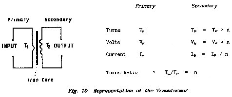
Each primary and secondary
"conductor" referred to above is shown as a single turn of wire wound
around a common iron core which is indicated by the solid line drawn between
the primary and secondary coils. The purpose of the core is to concentrate
the magnetic field to ensure that all fields pass through all turns of wire
a condition which is termed maximum coupling between the conductors.
The designations primary and secondary are
ours and are introduced to identify the different coils; as far as the
transformer is concerned they are all just lengths of wire wound around the
core and so it is to be expected that,
irrespective of which turn actually carries the primary current, ALL
TURNS carry equal secondary currents.
** If the turns are equal in every way and
they carry equal currents then it follows that equal p.d.s must be developed
across them. Thus, if the primary consists of a single turn and a secondary
consists say of three turns, it is to be expected that the p.d. developed across
the secondary is three-times that which appears across the primary?
** There
is a general rule therefore that the ratio
secondary p.d./primary p.d.
must
equal the ratio
no. of turns on secondary winding/no. of turns on
primary winding.
This is always referred to as the turns-ratio of
a transformer and it is usual to quote it as Output/Input as given above; sometimes,
either for clarity or convenience, transformers are referred to as step-up
or step-down transformers which is intended to show the manner in which the
voltage changes as the signal progresses from primary to secondary.
The above is a very simplified approach to
the transformer and full treatments in every degree of detail are given in
many textbooks. The discussion here is sufficient for the purpose of
the R.A.E.
As shown already the magnetic fields of secondary
currents tend to cancel the magnetic field of the primary current. In
a transformer where the secondary winding has more turns than the primary winding
there is an obvious difficulty in that the sum of the secondary fields is likely
to either obliterate the primary field (transformer action would cease) or
even reverse it. In that a transformer works it has to be concluded that,
as the turns ratio is increased (and the voltage ratio also is increased), so
the current ratio between secondary and primary must decrease.
** In Lesson-1 under 1.3.2: Work and Power it
is stated that the power dissipated in an electrical circuit is obtained by
multiplying the voltage by the current.
A transformer is an inactive device and does not have any means of generating
additional power; it does not get particularly hot and so it does not
dissipate any appreciable power. If the power-output is to be equal to
the power-input then the product of volts and amps in the primary circuit must
equal the product of volts and amps in the secondary circuit.
** A most important aspect of transformer behaviour therefore is that,
as it steps the circuit voltage either up or down, so it must step the circuit
current either down or up in an exactly inverse ratio. This is written in mathematical
terms as follows:
Let the turns-ratio be n ; let the primary
voltage be Vp ; let the secondary voltage be Vs ; let the primary current
be Ip ; let the secondary current be Is
THEN n = Vs/Vp =
Ip/Is
This matter is referred to again when dealing with Impedance Matching
1.10.2 Balanced Circuits
** Although alternating or varying signals can pass between the
windings of a transformer the lack of a conducting path between those windings
means that dc signals are blocked. As a consequence it is possible for
the different windings of a transformer to be at different potentials. Such
a potential difference is not confined to direct potentials and it may be either
a varying direct voltage or an unwanted alternating signal.
Unwanted or noise signals
appear in circuits through stray capacitive or magnetic couplings (see under 1.7.3,
1.7.4, 1.9.6) and it is usual to minimise these couplings by
earthing a circuit at some convenient point.
** The transformer offers a useful technique in the form of the
balanced circuit. Fig.11 shows the two
conductors of an electric circuit (perhaps a telephone cable) connected between
two transformers; the input to the first transformer and the output
from the second each have one leg earthed and so, in those parts of the circuit,
the signal information is carried only on the one (non-earthed) wire. Such
circuits are said to be unbalanced.
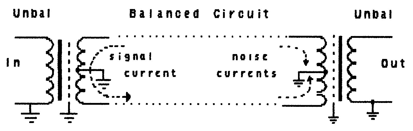
Fig. 11 Use of Screened Centre-tapped Transformers to Create
a Balanced Circuit
The remaining two transformer windings are
each centre-tapped and those centre connections are
taken to earth. Signal currents in this part of the circuit are carried simultaneously
on both wires but, at any instant in time, the two currents flow in opposite
directions. Such an arrangement is sometimes said to be operating in push-pull; one
leg is
"pushing" the signal while the other is "pulling".
Each wire carries the same value of current and the same voltage but, with
respect to earth, the voltages are of opposite polarity and the circuit is
described as balanced.
** There are many reasons for requiring a balanced circuit but,
in terms of noise suppression, it results in stray signals being injected equally
into both legs of the circuit. The two noise signals travel along the balanced
cable in the same direction and are sometimes described as being in push-push. At
the delivery end of the balanced circuit the wanted signal (in push-pull) is
transferred from the primary to the secondary winding but the noise signals
(in push-push) flow in opposite directions through the halves of the primary
winding and so cancel.
In telephone cables such transformers are known
as repeating-coils; they are carefully
balanced and their purpose is to prevent cross-coupling between the many pairs
of wires in the telephone cable.
** Transformers of various kinds which are used to couple
balanced circuits to unbalanced circuits are known as bal to unbal
transformers and have acquired the
composite name balun. They incorporate
a Faraday Screen (see under 1.9.6) between the two
windings to eliminate stray capacitive couplings that otherwise would destroy
their balance; this must be earthed.
1.10.3 High-frequency Transformers
** In the above discussion transformer windings were said to
be wound on an iron core to ensure efficient coupling between them. However,
to magnetise an iron core and to constantly reverse that magnetisation, consumes
power and the consequent hysteresis losses increase
as the frequency increases. Coupled with eddy-current losses this restricts
the usefulness of iron-cored transformers roughly to the audio band; i.e. 50
Hz to 20 kHz.
** The comments on iron-cored Inductors under 1.9.3 apply
equally to iron-cored transformers. For high-frequency working
it is usual for one or both transformer windings to be resonated as described
later under Resonance and Bandwidth. As
with variable inductors the inductance of each winding may be adjusted by use
of screw-in ferrite or copper cores.
** For very-high frequencies and for high-power working air-cored
self-supporting windings are used which can be fine-tuned by either stretching
or squeezing the coils; the distance between windings may also be adjusted
to control the degree of coupling between primary and secondary; see also under Transmitters.
** Note that the coils are self-supporting because they are made
from large-diameter wire to reduce skin effect (see under 1.9.4.).
 |
1.10.4 The Autotransformer
The discussion of Inductance under 1.9.1 was
extended to Self-inductance under 1.9.2 by eliminating
the secondary winding. The same argument can be applied to transformer
action in that a single winding can serve both as primary and secondary.
** Fig. 12 shows at
(a) a step-down transformer in which one leg of each winding
has been " commoned". In diagram
(b) the secondary winding has been omitted and the output is taken
from a tapping point at y on the primary. This
arrangement is known as an autotransformer; diagram
(C) shows a balanced form which is often met in transmitters. |
Because the primary turns carry a current which
is common to them all it can be deduced that the applied emf is divided equally
across them. Thus the ratio output-voltage/input-voltage is
given by:
number of turns yz / number of turns xz.
** The autotransformer is suitable only for small step-up or
small step-down ratios but it does provide a saving in the amount of copper
required and in the copper-losses in comparison
with an equivalent double-wound transformer. It
is necessary however to be aware of its shortcomings especially when used
with mains power supplies:
1. There is a direct connection between input and output
circuits.
2. Should a break occur in the common part of the winding
then the input emf is applied directly to the output (another reason for limiting
the step-down ratio).
3. Part of the winding must be wound with wire that is
thick enough to carry the larger current while the whole device must be insulated
to withstand the larger voltage.
4. A very dangerous situation arises in mains applications if the output
is inadvertently taken from across xy .
** The Autotransformer is used a great deal in aerial-matching circuits
and in the final (P.A.) stages of transmitters. It is also the
basis of the "Variac" transformer which supplies a variable-voltage
supply from the mains by making the tapping-point into a sliding contact. When
using a Variac always check its coil for continuity, make sure that the
output connections are taken from the correct points and do not exceed the
recommended current loadings.
1.10.5 The Toroidal Transformer
This consists of a small-diameter helix of
wire which is wrapped (like a collar) around a conductor; the conductor
forms the primary winding of a transformer and the helical coil forms the secondary. The
magnetic field of the primary follows the same path around the conductor as
does the helix and so they are linked.
The device forms a useful way of measuring
ac without interrupting the primary circuit and is the basis of the many instruments
often described as claup meters which are simply
clamped around any conductor in which the current-flow is to be measured. In
these meters the coil is wound in standard fashion on a two-part soft-iron
core which forms the jaws of the clamp.
The toroidal transformer, often wound on a
toroidal (ring) core, is also the basis of the so-called bridge arrangements
used in standing-wave-ratio meters which are described
in Part 7 of this Course.
A version of the toroidal transformer is sometimes
created in which both primary and secondary windings consist of a single conductor; such
a current transformer is achieved by laying the two
wires side by side and threading a suitable ferrite bead over
them. It can be a useful means of checking alternating current-flow where
space is more important than absolute accuracy.
Paragraphs marked with a double asterisk contain material
which is relevant to the RAE; the remainder form a continuous explanation.
1.11 AMPLIFICATION
** Amplification is the technical term for deliberately increasing
the strength (the amplitude) of a signal. The
reverse operation, that of starting with a too large signal and cutting it
down to a practical value, is called attenuation.
There are two ways of increasing size:
(i) a snowball set rolling downhill gathers snow and steadily increases
its bulk
(ii) a marine architect may first build a scale model of his ship and then,
with the problems under control, set about building the full-scale version; to
do this he takes a supply of new materials and ends up with both the model
and the finished ship.
In engineering the process of amplification uses the second method.
The first steam engines were built in Cornwall
to raise flood water from the mines; these engines did not operate continuously
but required constant driving.
Basically steam was raised at high pressure in a boiler and was then allowed
to enter a cylinder in which it pushed a piston to and fro; ultimately
the piston movement, with the power of the steam boiler behind it, was used
to raise water to the surface.
Steam was guided through the engine by a man
who used the relatively-puny power of his hands to operate steam-control valves.
Thus the result of simple low-power hand movements was that tons of water were
raised through several hundred feet.
Such power-controlling work systems are known as servo systems.
It could be said that the power of the steam boiler through the agency of the
steam engine amplified the power of the man; in
addition the man provided a controlling intelligence that, in turn, was guided
by signals received from the engine through his eyes and ears. Modern engines
move their own valves but the principle remains.
** An electronic amplifier performs the same function. It
requires an auxiliary source of power from which it fashions a new higher-power
output signal; the form of the output signal is determined by copying
the form of a low-power input signal (the control signal). The
device on which the input signal operates to control the power-flow is called
an active device because it actively does something; in
the steam-engine system described above the active device was the steam valve;
in the overall water-raising system the active-device was the steam engine. In
electronic amplifiers there are a variety of active devices but the most notable
are the thermionic valve and the transistor which
are described in detail in the Lesson on Electronic
Amplifiers .
** All amplifying systems, from the engine through horse-and-cart
to the domestic Hi-Fi system,
incorporate the basic requirements:
1. A source of power sufficient to meet the required demand
2. An active device to control the flow of power from the auxiliary source
3. A control signal - an input signal -which decides the form of the power-flow
by controlling the action of the active device
4. A source of information which originates the control signal (a generator)
..
** Fig.13 shows the basic
layout of an amplifier and Fig. 14 shows a very important
variation. The variation was mooted above when it was stated that modern
engines move their own valves. Some of the work output is tapped-off
and fed back to the control-signal to provide a secondary
control of the power-flow. Such feedback control takes
many forms and often goes unrecognised.
For example: at the end of the piston's
stroke the steam must be shut-off and an exhaust valve opened to allow the
spent steam to escape as the piston returns for the next power stroke. A
lever system which links the valves and the piston can do this job and so dispense
with the bored engineer and his twiddling hands; properly engineered
against mechanical failure this feedback lever-system will never get bored
and so will never make mistakes.
Yet again, without the engineer to watch and control it, the engine might overspeed
and so destroy itself. As shown in in Fig.
14 a sensor can be fitted which measures the speed of the engine
(against a reference which is provided for the purpose) and generates an
error signal; this low-power signal is fed back to control
the steam input to the engine in such a manner that it corrects any tendency
to depart from the required speed. This "correct" speed is
set by the reference signal which now becomes the speed control or throttle.
** The kind of feedback system described above, which operates
so as to maintain control and order, is referred to as negative
feedback because the error-signal is used to cancel or to negate any
errors.
Negative-feedback (n.f.b.) systems at their most simple are exemplified by
the mechanical flywheel which
(a) is difficult to start spinning
(b) once spinning is difficult to stop
(c) has a preferred spinning rate namely the one it already possesses.
In short, flywheels like to preserve the status quo - they
dislike change and oppose acceleration. Indeed n.f.b. systems not
only behave like flywheels but, in electromechanical systems such as video-recorders,
they are actually used as flywheels because they can be switched-off when their
conservative nature becomes inconvenient. They are also more compact and less
lethal than mechanical types.
** In the example given above it was the engine speed that was
measured and the result was used to control the engine speed.
This circular action gives rise to the technical term "feedback loop".
Note that, whatever is sampled in the measuring process, it is the sampled
parameter that is controlled.
** In electronic equipment the output may take the form of either
a voltage waveform (with negligible ability to supply current) or a current
waveform (with negligible ability to develop voltage); if both
voltage and current waveforms are required then it is necessary to use a power-amplifier. If
a feedback sample is derived from the voltage waveform then the voltage waveform
is maintained accurately at the expense if need be of the current waveform. If
a feedback sample is derived from the current waveform then the current waveform
is maintained accurately at the expense if need be of the voltage waveform.
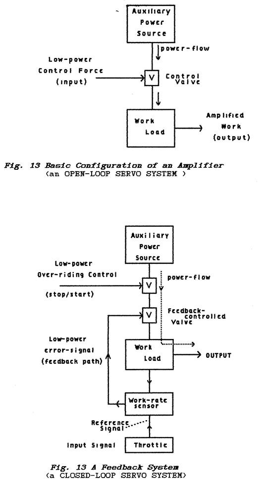
** To talk of negative-feedback implies that
there is a positive-feedback (p.f.b.) system and it is so; where the feedback
loop is connected so that the error-signal helps an error instead
of negating it then chaos results. Hard perhaps to believe but there
are conditions under which p.f.b. can be helpful; for example it is a
most effective way of speeding-up some operations but the Designer must be
careful to keep matters under control. Positive feedback is the essence of
systems which continuously oscillate (such as a clock pendulum or an electronic
oscillator ); control is maintained by a system that
restricts operation to a narrow band of frequencies (see Lesson on Electronic
Oscillators).
In particular most p.f.b. systems are controlled by a n.f.b. loop.
END OF LESSON 5
* * * * * * * * * * * *
QUESTIONS
1. What is meant by the "Turns Ratio" of a transformer
? How does this ratio relate: to
(a) the input and output voltages
(b) the primary and secondary currents ?
2. What is the thinking behind a balanced circuit?
3. What is a Balun?
4. In what manner do Audio Transformers and HF Transformers differ?
5. Why would you not use an Autotransformer in the power supply circuits of
a piece of equipment?
6. An amplifier increases the level of a signal and a transformer can be used
to step-up the voltage of a signal. Why is the transformer never referred
to as an amplifier?
7. In feedback systems what is it that is fed-back? What is the purpose of
such a technique?
8. Can you state briefly the different effects of positive and negative feedback?
Back to Top of Page
LESSON 6
1.12 Resistance, Reactance, Impedance, Q-factor
1.12.1 Resistance and Ohm's Law
In the previous Sections it was shown that conductors have
a natural resistance to the flow of electric current and that, when a current
varies, the natural resistance apparently increases because of inductive reactance.
Although all conductors must exhibit inductive effects there
are so-called non-inductive resistors. One
popular method of constructing these is to take a length of wire which has
the required resistance, fold it at the centre and then wind the doubled
wire on to a former taking care that the twinned conductors are kept in close
proximity. The idea is that current flows in opposite directions along
the two parts of the wire and so their magnetic fields cancel. Apart
from their awkward bulk such components can be very effective and are often
found for example in multimeters (test-meters) which function over a range
of frequencies.
This Section is concerned with true (non-inductive)resistance and so it is
applicable only to circuits which handle dc, very-low-frequency ac or to non-inductive
components.
Consider several conductors which are alike in every detail;
they are made from the same material, they have identical widths (W), identical
thickness (T) and identical length (L). When such identical conductors
are all connected across the same source of emf it is to be expected that
they will all draw the same current I amps.
Fig.14(a) shows one of these conductors
connected across a source of emf; the current I sets-up a p.d. across
the Resistor and that p.d. must be equal to the value of the emf (else the
current increases or decreases until equilibrium is attained).
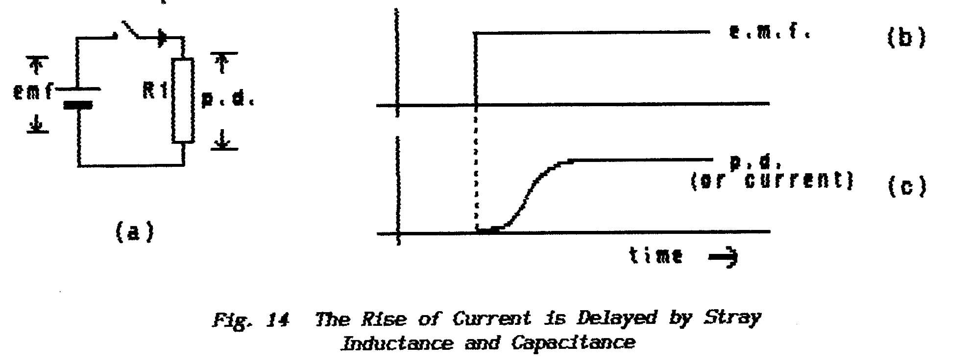
Fig.14(b & c) shows two graphs; the
upper one shows the variation of the applied emf with time and the lower shows
the variation of
the p.d. At the moment the switch is closed the applied emf leaps
instantaneously from zero to the value of the cell's emf but the p.d. builds
slowly to this final value. This is because the current is prevented
from changing instantaneously by the delaying effects of both inductance and
stray capacitance
In a similar manner, when the switch is opened,
the applied emf falls instantaneously to zero but the current - and therefore
the p.d. across the resistor - falls slowly. There is a philosophical problem
here in that, after the switch has been opened, the current has nowhere to
flow and so it should also fall to zero instantaneously. Consider that,
for the current to fall at all, a mechanism is required to discharge both the
stray capacitance and the magnetic field. This is usually explained in
terms of the spark that jumps the switch contacts as an inductive circuit is
broken.
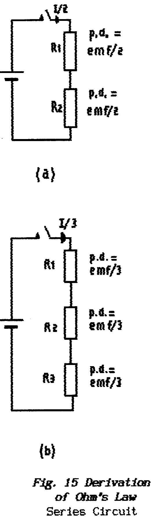 |
** Fig.15(a.)shows
two of the identical conductors connected across the cell in a manner
that requires the current to flow first through one and then through
the other. The conductors are said to be connected in
series or to be series-connected.
Because the one current flows through the identical resistors
it must develop the same p.d. across each and so equilibrium is established
when each p.d. is equal to half the applied emf. It follows that
the current which flows through two identical resistors in series must
be half that which flows through one of them when connected to the
same emf (Fig.14).
The exercise is repeated in diagram
(b) with three series-connected resistors to show that the current
has to fall to a value I/3 so as to produce a p.d. across each resistor
of emf/3. From this it is possible to deduce a general rule
that, when n conductors are connected in series, the current falls
to I/n so that the individual p.d.'s fall to emf/n.
** This simple relationship is the subject of Ohm's
Law which states that in association with any given conductor, the
ratio of voltage-to-current is always constant; that constant
is known as the resistance of that conductor.
The Law is expressed in symbols as:
E/I = R
where E is the voltage in volts developed across
the conductor, I is the current in amps which
flows through the conductor and R is the resistance
of the conductor which is expressed in ohms.
** Given any two of these quantities the third can
be calculated by manipulating the expression (see Lesson on Algebra).
E = I.R or I
= E/R
Again it is best to remember only one of these
relations and to obtain the others
by cross-multiplication as required. |
| Fig.16 shows two identical conductors
connected to a source so that a current flows through each of them independently; connected
in this way they are said to be connected in parallel or
to be parallel-connected Once
again the p.d.'s developed across each conductor are identical (equal
to the source emf) but the source is called upon to supply twice as much
current. When three conductors are connected in parallel the current
in each stabilises at a value I, the p.d. across each conductor stabilises
at the value of the emf and the total load current drawn from the source
becomes 3.I. |
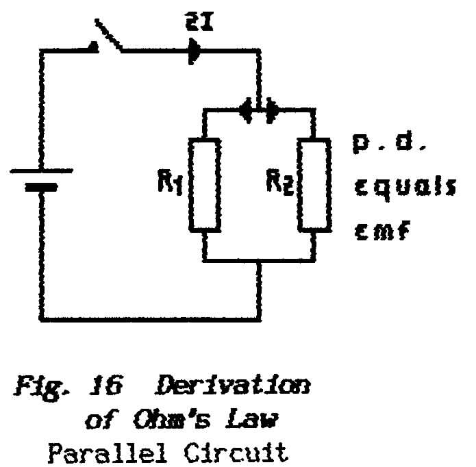 |
** Because the current demanded increases with the number
of parallel-connected conductors it would appear to the source that the load
resistance presented by n conductors each of resistance R looks like R/n.
** In practice however it is fairly unusual to
be connecting identical resistors in parallel or in series. With series connection
the resulting total resistance is straightforward. Although they are of different
values the resistors carry the same current and so they develop different values
of p.d.; these individual p.d.,s sum to the value of the emf. Draw
a diagram similar to Fig.15 and you will see that
the total effective resistance Reff is given by R1 + R2
+ R3 + . . . .
** Different resistors connected in parallel produce a more complicated
calculation because it is now the currents which sum instead of the p.d.'s
and current (I) is on the bottom line of the equation E/I
= R. For the RAE you are not expected to derive these
formulae only to be able to quote them and use them. For resistors in
parallel the total effective resistance is given by
1/Reff = 1/R1
+ 1/R2 1/R3 + .
. . . .
For two resistors in parallel this is usually remembered as
product-over-sum
Reff = R1.R2
R1+ R2
** There is sometimes a requirement to find the equivalent
resistance of a network which combines parallel-connected resistors and series-connected
resistors. The rule is:
(i) reduce all parallel-connected groups
to single equivalent resistors
(ii) collect all series combinations to single equivalent
resistors
(iii) repeat steps (i) &
(ii) until only one equivalent resistor remains.
Under 1.3.2 it
was shown that the power dissipated in an electrical circuit is obtained by
multiplying together the values of electrical pressure (volts) and electrical
flow-rate (amps); for a purely-resistive (i.e. non-reactive) circuit
this is expressed in symbols as
P = E x I
where P is the power in watts, E is
the voltage applied across the component (or the p.d. developed across that
component) and I in amps is the current which flows
through the component.
** However the two parameters E and I form
part of the expression for Ohm's Law and so
it is possible to express power in terms of the circuit resistance; in
the above expression for power the product I.R can
be substituted for E or the ratio E/R can
be substituted for I which yields either
P = I.R
x I = I2 .R or P = E
x E/R = E2/R
(These two variations should be remembered.)
1.12.2 Inductive Reactance
Under 1.9 it was
stated that, when the current which flows in an electric circuit varies in
value, then there is interaction between the electrical path and the surrounding
magnetic field. This interaction causes the current to fall to a value
below that predicted by Ohm's Law. This result is usually interpreted as
an increase in the apparent resistance of the conducting path but matters are
not at all so delightfully simple.
A basic experiment in the early study of electricity
and magnetism shows that current can be induced in a coil of wire by moving
a permanent magnet in the vicinity of the coil. It is easily established that,
although the strength of the magnet is important, the major factor which controls
the rate of current-flow is the speed of the magnet. relative to the coil. The
greater the rate of relative-movement (the greater the rate at which the magnetic
field changes) so the greater is the induced electric current.
** In a circuit which carries ac the rate at which the associated magnetic
field varies is controlled by the frequency of the ac; it follows therefore
that, as frequency is increased, so also does the induced (the opposing) current.
Thus the apparent increase in resistance to an alternating current becomes
more pronounced as frequency rises.
** Note that the "proper" resistance of the conductor remains
unchanged and this is usually referred to as the dc resistance.
It is only the apparent increase in resistance - the inductive reactance -
which is proportional to frequency; this reactance must be added
to the dc-resistance to obtain a prediction
of the overall behaviour of the electric
circuit ( see below under 1.12.4: Impedance)
** The inductive reactance of a conductor (or of an Inductor) is given
the symbol XL and is expressed in ohms. Where
the inductance has a value L (Henrys) and the frequency
is f (Hertz or cycles-per-second) the inductive
reactance is given by
XL
= 2חfL
The constant 2ח arises
because frequency is measured as the number of revolutions per second of a
vector and each complete revolution is expressed as 2.ח radians
(see under 7.2: Trigonometry). The
combination 2חf recurs frequently in ac theory
and it is convenient to replace it with the Greek symbol omega (lower
case) ω . Thus
the above expression is more usually written as
XL = ωL
(ω is known as the angular velocity in that
it defines the number of radians traced out every second - it defines
the rate of change).
The above expression for inductive reactance
is shown in Fig.17 as a plot of reactance against
frequency (see under 7.3: Graphs). Because
all terms are in linear measure (i.e. the expression does not include squared
or higher-order terms) the graph is a straight line although we still refer
to it as a curve. We say that reactance,
inductance and frequency are linearly related. The full line shows
the variation of XL with
frequency; note that at zero frequency (i.e. dc) the reactance is zero. The
broken line shows the practical result when dc-resistance is added.
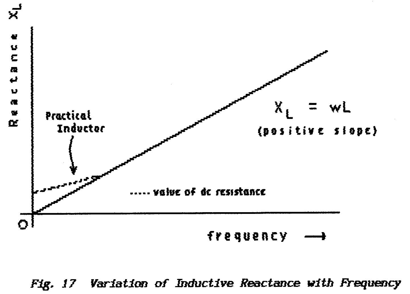
** The difference between dc-resistance and inductive reactance
lies in the relative timing of current and voltage waveforms.. In a truly resistive
circuit the current. is always related to the voltage by Ohm's Law. If
the current and voltage values are sampled at any instant of time the ratio
always yields the same figure. In a reactive circuit, either inductive
or capacitive, this is not so.
The flywheel-like
action of inductance (see under 1.9.2) causes a
circuit to resist changes in current flow and this means that a period of time
is required for current either to increase or to decrease in value. In
an ac circuit the applied emf constantly cycles and the resulting current,
although it varies in value with the same waveform, is delayed with respect
to the voltage waveform.
In Lesson-2
of Trigonometry (under Mathematics) a sinewave is derived
as a result of rotating a vector; in this waveform the amplitude
is proportional to the sine of the angular displacement. Such a sinewave
is shown in Fig.18 where, in diagram (a), it represents the alternating
emf applied to an inductor.
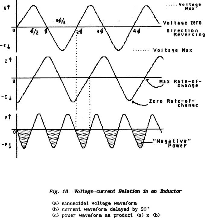
Diagram (b) shows
the waveform of the current which flows through the Inductor; it
is shown as delayed by a ¼-cycle or 900.
In fact this is the delay (or the relative phase-angle) that would be caused
by a theoretically-perfect Inductor which would have zero dc-resistance. In
a practical Inductor the presence of resistance reduces the relative phase-angle; as
the resistance is increased so the phase-difference moves toward zero as the
component changes from an effective inductor to an effective resistor.
Note that, because
inductive reactance is proportional to frequency so the relative
phase-angle moves towards 900 as frequency rises. However the general
result of increasing the frequency is that an Inductor becomes less efficient
(or more "lossy") and this reduces the phase angle. (It is shown
below that power cannot be dissipated in pure reactances and so losses must
be represented as the presence of resistance.)
In a pure inductor
the 900 relative-phase between current and voltage is often described
by saying that the two parameters are in time quadrature; the
expression simply means that they are displaced in time by 900. .
(The electric and magnetic components of the field radiated from an aerial
are mutually at right-angles and are said to be in space-quadrature; see
under 2.4: Aerials.) It is usual
to drop the adjective and simply refer to them as being "in quadrature".
Note that current
maxima occur where the voltage is zero and is undergoing its maximum rate-of-change; current
minima occur where the voltage is at maximum value with zero rate-of-change.
** Under 1.3.2 it was shown that the
power dissipated in a circuit is obtained by multiplying together the values
of voltage and current. When using alternating current this can
be done only on a point-by-point basis; for each value of angle
(along the horizontal axis) the instantaneous values of current and voltage
are selected and multiplied with the result shown in Fig 18(c). (See
also in Mathematics under RMS Va1ues). When
two positive values or two negative values are multiplied the result has a
positive sign but, when either the voltage or the current (but not both) are
negative, the product has a negative sign.
** Fig.18 (c) appears to indicate that
power is first drawn from the source for a
¼-cycle and then returned to the source during the following
¼-cycle. However this is a mathematical result and requires
interpretation; clearly the average power during each whole cycle is
zero. For this reason a purely reactive component - one in which
the voltage and current are in quadrature - is said to draw a wattless current.
** All practical components possess dc-resistance and this causes
the voltage and current waveforms to depart from exact quadrature; current
which flows through the dc-resistance causes the dissipation of power. This
problem is dealt with in calculation by treating each practical component
as two separate "pure" components namely a perfect inductor in series
with a perfect resistor; the voltage waveform developed across
the pure resistor is in phase with the current and so power is dissipated; the
voltage waveform developed across the pure Inductor is in quadrature and the
theoretical component does not dissipate power.
** Clearly the two voltages cannot be added directly although
they must sum to the value of the applied emf; this matter is dealt
with under 1.12.4 Impedance.
END OF LESSON 6
* * * * * * *
* * * * *
QUESTIONS
1. What is a non-inductive resistor ?
2. , Three resistors each of value 300 ohms are connected (a) in
series and (b) in parallel; what is their effective value In
each arrangement ?
3. Two of the resistors are connected in parallel and the third in series
with the combination. What now is their effective resistance?
4. What is the voltage developed across the 50-ohm feedpoi.nt of an aerial
which is accepting 50 watts ?
5. What is the difference between a purely-resistive circuit and a practical
circuit (one that contains reactance) when they carry ac ?
6. Given that you have a normal multimeter (measures amps, volts
or ohms either ac or dc) what can you measure about an inductor ?
7. What effects would you expect to observe when an inductor is connected
to a dc source ?
8. An emf is applied to a resistor; if the emf is doubled
in value what do you expect to happen to the current flowing through the resistor
?
Which Law of Physics enables you to solve this question simply ?
9. CATCH QUESTION If the emf applied to resistor
is doubled in value what do you expect to happen to the power that is dissipated
by that resistor ?
Back to Top of Page
LESSON 7
1.12.3 Capacitive Reactance
** A capacitor of course does not pass a direct current and
its ability to pass alternating current is more a matter of effect than reality.
However, as with an inductor, the current and voltage waveforms do not vary
in step; in a loss-free capacitor they are in quadrature. There
is a significant difference however in that capacitive current is advanced
with respect to the voltage as distinct from inductive current which lags behind
the voltage.
It is reasonable to ask how the current is
able to lead on the voltage; how could the current know what the voltage
is going to do in the immediate future ? The answer is that this relationship
is possible only with recurrent waveforms; information which controls
current flow comes from the preceding cycles. In effect the current is
not so much a quarter-cycle in advance as three-quarter cycle lagging behind
and this can be deduced as follows:
** Alternating current flows in the connections to a capacitor and alternating
p.d.s build-up between the capacitor plates. The current in the connecting
leads falls to zero as the capacitor p.d. reaches its peak value; current in
the connecting leads reaches its maximum value as the capacitor p.d. falls
to zero (as the p.d. reverses polarity) and the capacitor begins to re-charge
with the opposite polarity.
** As with inductors this quadrature relation between current
and voltage means that the term capacitive-reactance must
be substituted for resistance.
** Alternating current which flows in the connections to a capacitor
represents the charge (the number of electrons) which is being moved in and
out of the capacitor ; thus the larger the capacitance the greater the
amount of charge to be moved and so the greater must be the alternating current.
Such an increase of current (as a result of an increase of capacitance) is
interpreted through measurement as a decrease of reactance.
As the frequency of an ac is increased so the
capacitor is allowed less and less time in which to charge and discharge and
so the alternating p.d. which develops across it is reduced - given that the
value of the ac remains constant.
According to Ohm's Law the p.d. is the result of multiplying current and
resistance or, in this instance, current and reactance. If the value of the
ac remains constant as the p.d. decreases then the fall of p.d. with increasing
frequency has to be interpreted as another fall in reactance.
** Thus capacitive reactance (Xc) falls
when either the capacitance or the frequency is increased and this is expressed
in mathematical symbols as
Xc = 1/(2πfC)
where the capacitive reactance (Xc) is in ohms,
the frequency is expressed in circular measure as 2πf radians per second
and the capacitance (C) is in Farads
Again it is usual to insert the Greek symbol w for the angular frequency and
the above formula becomes
Xc = 1/ωC
The expression for Xc. is plotted in Fig.19.
Although all the terms are linear the result is not a straight line because
of the inverse relationship. As frequency falls toward zero (dc) so the capacitive
reactance increases toward an infinitely-large value (an open-circuit) ; at
the other end of the curve, where frequency is rising toward an infinitely-large
value, so the value of the reactance is falling toward zero (a short-circuit).
Note that at each end of the curve there is
a gradual approach to the relevant axis although, in theory, contact never
occurs. We say that the curve is asymptotic* to (in
this instance) both axes. In practice the actual point of contact is of no
importance because, as the interval becomes smaller, so the curve gets lost
in the vagaries of measurement - we say that it falls below the noise
level
As with inductors the quadrature relation between
current and voltage causes capacitors to draw a wattless current. Capacitors
too have dc-resistance, both in their connecting leads and in the plates themselves,
and there are other losses associated with the dielectric ; all these
combine to reduce the relative phase-angle below 900 degrees. In
terms of Fig.19 this causes the right-hand end
of the curve to be asymptotic to a line slightly above zero ohms and this line
represents the effective dc-resistance (the losses) of the capacitor.
** Because the current that flows through a capacitor leads the applied
voltage by approximately 900 while that which flows through an inductor
lags the applied voltage by approximately 90 then, in any
circuit which contains both components, the two currents must be nearly 180-degrees
out of phase; in other words they must tend to cancel. The opposing nature
of capacitive and inductive reactances
____________________________________________________________________
* Pronounced a - simp - totic
are shown mathematically by placing a minus(negative) sign before
the symbols or figures for capacitive reactance.
Hence the expression given above for capacitive reactance should be written
as
Xc = - 1/wC
The negative sign ensures that, when an expression
is written to describe the overall behaviour of an ac circuit, the inductive
and capacitive reactances cancel each other automatically;
for example, a circuit which contains resistance, inductive-reactance
and capacitive-reactance is described as R + wL
- 1/wC
** Although resistance and both forms of reactance inevitably
occur in the same circuit their overall effect cannot be expressed simply by
adding together their individual values in ohms. For the series resistive circuit
considered under 1.12.1 (Lesson-6) the overall
resistance was found by adding the individual p.d.'s and dividing by the
common current ;
for the parallel circuit the overall resistance was found by adding together
the various currents and then dividing the total into the common p.d. For an
ac circuit neither voltages nor currents can be added directly unless they
vary in sympathy; i.e. either the circuit is free of all reactance or
the inductive and capacitive reactances exactly cancel (see later under 1.13:
Resonance)
The solution to this problem is geometric using
vector addition. A vector quantity is simply one which indicates
direction as well as size (magnitude). For example it is correct to say
that a car travels at a speed of 30 m.p.h. but, to be credited with a velocity,
it must be given a direction such as 30 m.p.h. due east. Speed is a scaler
quantity - it indicates only scale or size. Velocity is a vector quantity. In
this example the motion of the car could be depicted graphically by an arrow
(called a vector) of length 3-inches pointing to the right where the scale
chosen for the diagram is 1-inch represents 10 m.p.h.
** The overall effective "a-resistance"
of a circuit which contains both dc-resistance and either or both forms of
reactance is given the name impedance.
The effective resistance or reactance which
is present in any circuit is measured by the amount of current which it permits
to flow for a given applied emf. Fig.20 (a) shows
three vectors:
(i) an arrow AS whose length represents the dc-resistance (magnitude of the
direct current) which, by choice, is drawn horizontally
(ii) a second arrow BC whose length represents the
inductive reactance (magnitude of the alternating current); current which
flows through this reactance leads by 900 and so the vector is drawn
at 900 to the resistance vector but rotated anticlockwise
because this is the standard agreed in mathematics for positive-rotation (inductive-reactance
is given a +ve sign).
(iii) a third arrow AC which shows the overall effect of the first two and
which is therefore a vector that indicates both the magnitude of the resulting
impedance (Z) and the phase-angle between the applied
voltage and the resulting alternating current.
It is perhaps easier to justify this vector-addition
if the scenario is changed; consider AB as the velocity of an aeroplane
flying due east while BC represents the motion of the air (the wind) which
is blowing toward the north. The aeroplane may travel from A to C either by:
(a) traveling along AB in still air for a given time and then remaining stationary
with respect to the air while the wind blows for the same period of time
(b) traveling directly from A to C by flying vector AB at the same time as
the wind blows vector BC; the arrow AC represents the track over the
ground as the aeroplane progresses simultaneously along both AB and BC. Thus
AC is a vector whose length represents the true speed over the ground and whose
direction shows the true direction of travel.

This technique can be used to add resistance
to reactance, reactance to reactance or to find the resultant waveform when
two out-of-phase waveforms are added; it can be extended to sum any number
of such quantities. Fig.20(b) shows the vector diagram
which is used to add resistance to capacitive-reactance and diagram (c) shows
the construction to add resistance to a combination of both kinds of reactance. Note
that the reactances and the resistances (all
"like" quantities) are summed first before vector addition of unlike
quantities is attempted.
The above method using vector diagrams is a
valid way of adding vector quantities and, where it is required to add several
such quantities, it may well prove to be the best method. It can also
be the best method when the quantities involved are not in exact quadrature; see
under Mathematics: Vector Diagrams. For calculations
involved in electrical work, where practical problems are usually
concerned with essentially pure components, all that is required is the solution
to a right-angled triangle. As shown in Mathematics under Lesson-1 of Trigonometry this
can be achieved by use either of Pythagoras Theorem or
by using Trigonometry Tables.
** Pythagoras Theorem states that, in any right-angle triangle,
the square on the hypotenuse (the longest side) equals the sum of the squares
on the other two sides; with reference to Fig.20 this
relation is expressed as
AC2 = AB2 + BC2
which translates as
Z2 = R2 + X2
Thus the square of the Impedance can be calculated by adding together the
squares of resistance and reactance. Of the three quantities resistance, reactance
and impedance, if any two are known then the third can be calculated.
** A vector diagram also shows the relative phase-angle between
quadrature components. As shown in Fig.21(a) a
perfect inductor connected in series with a perfect resistor (which represents
a practical inductor) has a common-current I, a voltage across the inductor
VL, a voltage across the resistor VR and a voltage across the whole component
VZ ; this last must equal the applied emf.
In diagram (b) the current-vector I is shown
as a reference for direction; the voltage VR is drawn in phase with I
and the voltage VL is shown leading the common-current by 900.
Because the current is common the lengths of the two voltage vectors represents
also the magnitudes of the resistance and reactance; thus their
vector sum VZ represents both the applied emf and the magnitude of the impedance. The
angle φ (Greek letter phi) shows the angle by which the emf leads the
current which flows through the practical inductor (if preferred, it shows
the angle by which the current lags behind the applied voltage.
**From Fig.21 it can be deduced
that the relative-phase angle φ is given by
cos φ = VR/Vz =
R/Z
tan φ = VL/VR = XL/R
(see Lesson on Trigonometry)
** The quantity cosφ is
known as the Power Factor of that particular component. Remember
that the perfect inductor draws a wattless current ; any power that the
practical inductor dissipates must be consumed in the perfect resistor. The
Power Factor expresses the ratio between apparent power (the applied voltage
x the current ....known as volt-amps) and the
true power (p.d.-across-R x current). To obtain the actual
power dissipated in a reactive circuit therefore it is necessary to multiply
the apparent power in volt-amps by the Power Factor ;
i.e.
Power (Watts) = V x I x cosφ
** The quantity tan φ is
the ratio between perfect reactance and perfect resistance and so expresses
the
"goodness" of the component or the degree by which it departs from
being a perfect inductor. The ratio is known as the Q-factor ; for
example a Q of 1 indicates equality between the reactive and resistive components
while a Q of 1,000 shows that the inductor is close to being a perfect component.
END OF LESSON 7
* * * * * * *
* * * * *
QUESTIONS
1. What is the basic difference between the ac which flows through an inductor
and the ac which flows through a capacitor with respect to the applied
emf?
2. What other difference is there between these two currents in terms of frequency
?
3. In what way does resistance modify inductive and capacitive currents ?
4. Why is capacitive reactance written mathematically with a negative sign
? What is impedance ?
A circuit contains 3-ohms resistance and 4-ohms inductive-reactance; what
is its impedance ?
6. What is the significance of the Power Factor?
** Paragraphs marked with a double asterisk contain
material which is relevant to the RAE ; the remainder form a continuous
explanation.
Back to Top of Page
LESSON 8
1.12.5 Notation (not essential for RAE)
It is perhaps easiest to write
" R + X = Z " and to remember (hopefully)
that the addition must be made vectorially as discussed in Lesson 7 ;
i.e. first square R and X, then add the results and then find the square-root
to obtain Z.
This is not too difficult when looking at the symbols R and X but, once numbers
are inserted in place of those symbols, then the likelihood of error becomes
very great. As a reminder it is possible (and indeed sometimes done)
to add some kind of symbol to indicate that the quantities are vectors: for
example
R + X = Z
Such a notation however is clumsy and does
not readily lend itself to algebraic manipulations (where the requirement is
to solve a problem in general terms rather than to obtain an arithmetical answer).
The mathematical tool used to handle these expressions is the j-notation which
is described in detail in the Mathematics Lesson.
At its most simple a letter j is placed
before each item which is reactive thus for example
Z = 52 + j67
- j15 + 12 + ,j6
indicates that a series circuit consists of a 52-ohm resistance followed by
a 67-ohm inductive-reactance followed by a 15-ohm capacitive-reactance followed
by a 12-ohm resistance followed by a 6-ohm inductive-reactance.
Had the frequency been given these figures
could be interpreted in terms of inductors and capacitors but, without such
information, all that can be derived from the expression is the overall impedance
(at whatever the frequency may be).
The first step in this process is to collect together all the similar terms; to
make life even easier we put all the reactive terms together inside a set of
brackets and use a single j in front of the brackets
Z = 52 +
12 + j(67 - 15 + 6)
= 64 + j58
From this can be calculated:
(a) the impedance Z = √(642 + 582)
(b) the phase-angle φ between current and voltage = tan-1 (58/64)
(The notation tan-1 is mathematicians'
shorthand which simply means " ... the angle whose tangent
is ... ")
A full treatment is given in Mathematics but
here it is noted only that j is more than just an indicator of a quadrature
relation; it can be used very effectively in manipulating equations
and is known as an Operator. A quantity
expressed as R + JX is called
a complex quantity. These are sometimes
expressed in what are known as polar co-ordinates which
consist of a figure that gives the magnitude (Z) followed by an angle that
represents the relative phase angle; for example the above expression
64 + j58
becomes
√ (642 + 582), tan-1 (58/64)
The above discussion deals with a set of components
connected in series. When components are connected in parallel the formulae
derived from Ohm's Law deal in inverse quantities (see under 1.12.1 in Lesson-6). For
ease in handling these formulae a set of names has been given to the inverse
of resistance and reactances namely
1/resistance (1 /R) is
called conductance (G)
1/reactance
(1/X) is called susceptance
(B)
1/impedance
(1/Z) is called admittance (Y)
Thus in place of l/Z = 1/R + 1/jX we can write Y = G
+ JB.
The benefits of this alternative notation may
not be immediately evident until it is realised that Instruments for measuring
resistance/reactance can be built to give their results in either the normal
or inverted form. An Impedance Bridge gives
its results in terms of R and jX (a series-connected circuit) but
an Admittance Bridge gives results in terms of G
and jB (a parallel-connected circuit). Where measurements are made
with an Impedance Bridge the circuit is adjusted by adding extra components
in series (often difficult); where measurements are made with an Admittance
Bridge the circuit is adjusted by adding extra components in parallel.
1.12.6 Impedance Matching
** Consider two circuits both of which carry a signal at 10 watts.
Circuit A draws a current of 1-amp and so has 10-volts developed across it
(power = volts x amps) while circuit B draws a current of 0.1 amps (100 mA)
and so has 100-volts developed across it. The application of Ohm's
Law shows that circuit A has an impedance of 10 ohms but that circuit B has
an impedance of 1,000 ohms.
A problem arises when it is required to transfer
the 10-watt signal from circuit-A into circuit-B.
Because circuit-A can supply only 10 volts from which circuit-B will accept
only a maximum of 10/1,000 A (10 mA) it follows that the maximum signal power
that can be transferred from A into B is 100 mW or 0.1 W .
Additionally circuit-A is left with a surplus of 990 mA equivalent to
9.9 W which it has to dump somewhere.
** This inability to transfer power between two circuits because
they operate at different impedances is known as an impedance mismatch ; to
transfer the maximum possible power between two circuits it is essential that
their impedances match. Such a transfer can be achieved
between two un-matched circuits however by use of a suitable coupling arrangement
and the process is referred to as Impedance Matching ; basically
the trick is to find a device whose input impedance matches the impedance of
the source-circuit but whose output impedance matches that of the receiving-circuit
(the load).
** One type of matching device, the Transformer, has been discussed
already in Lesson-5. Note that the transformer cannot amplify signals
because it lacks any form of auxiliary power. Thus, when a transformer steps-up
the circuit voltage, it must at the same time step-down the circuit current
; an increase (or fall) in the circuit voltage accompanied by a decrease
(or rise) in the circuit current corresponds to a change of impedance as the
signal is transferred across the transformer from primary winding to secondary
winding.
** In the example above a matching transformer
required to transform the 10-volts of circuit-A to the 100-volts of circuit-B
would require a turns-ratio (n) of 1:10.
However the transformer is matching between a 10-ohm circuit and a 1,000-ohm
circuit; thus a turns-ratio of 10 produces an impedance-ratio of
100 and, in general terms, we can write that
impedance-ratio = n2
** Matching can be achieved also by using networks of inductors
and capacitors which are referred to generally as matching filters, matching
sections or simply as networks. It
can be achieved also by using networks of resistors although these produce
a reduction in the signal level, known as attenuation, that
may sometimes be a disadvantage.
These resistive networks are variously called attenuators or pads and
they may also be introduced into a system to provide only attenuation or to
isolate circuits that otherwise would mutually interfere. There are occasions
when all three functions are indistinguishable.
Detailed knowledge of filters and attenuators
is not required for the RAE but their use to cure or to avoid interference
is dealt with under 6.4: Measurements
and EMC. They are also introduced under Transmitters.
In general terms (i.e. not usually used in
Amateur Radio) impedance matching can be achieved also by using a feedback-amplifier
whose input and output impedances can be tailored to the required values;
these circuits are described in later Sections of this Course.
There is a Maximum
Power-transfer Theorem which
states that the maximum possible power is transferred between circuits
when their impedances are matched. As described under 1.15: Internal
Impedance this means that a maximum 50% of the signal
power can be transferred; the remainder is dissipated in the source circuit.
1.12.7 Component Q-factor
** Although a "pure" inductor as defined draws a wattless
current a practical inductor is wound with wire that has dc-resistance;
together with eddy-currents and stray couplings these cause losses.
Given the experimental technique it is possible
to measure each of these power-losses but, in general, such information is
of little use.
Interest centres on the total power consumed by the inductor and so all losses
are treated as though caused by dissipation as heat in a single theoretical
resistor.
One way of determining this total loss is to
measure the relative phase- angle between the current and voltage waveforms. A
more accurate method is to use an ac instrument called a Bridge which,
as already discussed, will show a reactance value in series with a resistance
value (an Impedance Bridge) or as a reactance value in parallel with a resistance
value (an Admittance Bridge). For a high-quality inductor the values of reactance
will not differ appreciably between the two methods of measurement but that
is not so for types with appreciable losses.
** An efficient (low-loss) inductor is indicated by either a
low-value series resistor or by a high-value parallel resistor but, with either
method of measurement, the ratio between resistance and reactance is the same. This
ratio is in effect a quality rating and is known as the Q-value. As
discussed above the ratio also describes the relative phase between voltage
and current waveforms.
** So far the Q-factor has been defined in terms of an inductor
but there is no reason why the idea should not be extended to a capacitor.
Although a capacitor does not provide a dc path between its plates it does
permit alternating currents to flow in its connections and also to flow across
the plate surfaces; where current flows there is a heating effect
which represents loss of signal power.
Additionally the dielectric dissipates a small amount of power. All these losses
are usually amalgamated into a single (theoretical) resistor which again can
be calculated as either a series resistor or a parallel resistor. Once again
an efficient component is characterised by a high Q-value.
Q-factors are involved also in resonant circuits ; see next Section.
1.13 RESONANCE
1.13.1 Introduction
** Resonance occurs in electric circuits which contain both inductive
and capacitive reactances ; inevitably resistance must be present
also but, although it modifies the behaviour of the circuit, it does not itself
play a significant part in the basic phenomenon of resonance.
Fig.22 Practical Inductor Connected
to a
Practical Capacitor |
Fig. 22 shows
a practical inductor and a practical capacitor connected together.
Assume that in some manner, perhaps
by electromagnetic coupling, a current has been induced to flow in
the inductor.
As discussed under 1.9.2 Self-Inductance the
inductor has a flywheel-like nature that tries to keep a current flowing
and which resists any changes in the rate-of-flow. As a consequence
the capacitor
collects all the available charge (all the free electrons) and so eventually
forces a cessation of current flow. Whatever energy was induced into
the circuit is now collected in the electric field between the plates
of the capacitor while the cessation of current-flow has terminated
the flywheel action of the Inductor. |
Thus the charged capacitor is now free to discharge
through the Inductor; in doing so, it causes a current to flow
in the reverse direction and so sets-up a new flywheel action to maintain that
reversed flow.
Once again, with the reverse current established,
the inductor remains in control until all the circuit energy is again stored
in the capacitor but this time with the polarity reversed.
This cycle must repeat and would do so endlessly
but for the practical reality of circuit resistance (and other small losses)
which slowly convert the stored energy into heat which, in the form of infra-red
radiation, is then lost from the circuit.
** This constant interchange of energy between two different
storage media is the mechanism of resonance; for
electrical resonance it is the interchange between:
(a) static or stationary charge held in the electric
field between the plates of a capacitor and
(b) dynamic or moving charge (an electric current)
where the energy is held in the accompanying magnetic field.
The rate at which this interchange takes place
is controlled by the amount of storage available and clearly must be a function
of both the capacitive storage and the inductive storage. The larger
the amount of storage so the longer is the period required to discharge one
of them in the process of charging the other; in other words, if either
the capacitance or the inductance is increased, the circuit must operate
at a slower speed and there are fewer cycles of operation per second.
** For any combination of inductance and capacitance there is
a preferred (or natural) rate of oscillation at which
the interchanging action takes place and this, reckoned as the number of complete
cycles per second, is known as the natural frequency or
as the resonance frequency of the circuit.
(It is common to see this frequency referred
to as the "resonant" frequency which implies that it is the
frequency which is resonating. The correct term is derived from the full
expression " the frequency of resonance ". )
** Resonance frequencies like all frequencies are expressed in
Hertz (Hz) where 1-Hz is defined as 1 cycle per second. In
an electrical circuit the frequency at which a combination of inductance
and capacitance resonates is given by the expression
f = 1/(2π.√LC)
where f is in Hz (cycles per second), L is in Henrys and C is in Farads.
NOTE This formula is required
for the R.A.E.
** The resonance frequency is found to be that frequency at which
the inductive reactance is numerically equal to the capacitive reactance ; if
XL is equal to -XC then the overall reactance in a resonant circuit is
zero and so, at resonance, the current that circulates between the two components
rises to a maximum value which is controlled only by the circuit resistance
RL + RC .
** Thus the resonance frequency is that frequency at which it
is most easy to cause current to circulate between the inductor and capacitor.
It is worth remembering that resonance is not
purely an electrical phenomenon but occurs in almost every aspect of everyday
life. The well-known leg is a pendulum hanging from the pelvic girdle
and it is moved with minimum effort by swinging it at its natural frequency
(see next Lesson). Hence, in developing the technique of locomotion, life
forms varied their speed by changing the length of each stride rather than
trying to change the striking frequency of the leg(s).
When walking, each leg remains in contact
with the ground for the majority of the time ; for two-legged locomotion,
such as is used by humans, one leg supports the body while the other moves
through to catch the body as it falls off the supporting leg. In the
trot only one leg remains in contact with the ground in a series of hops from
leg to leg. In the run both legs lose contact with the ground over most of
the running period as the runner leaps from leg to leg to gain the maximum
possible length of stride.
Quite simple tests will convince you that changes
in the striking rate of the legs are brought about by bending the
knees so shortening leg-length.
END OF LESSON 8
* * * * * * *
* * * * *
QUESTIONS
1. What is the purpose of using the letter j in calculations ?
What is the approximate impedance of a circuit comprised
of 7 + j7 ?
2. Why do we want to match one circuit to another ?
Given one circuit of 50 ohms and another of 200 ohms what
must be the turns-ratio of a transformer that will produce a satisfactory match
?
3. What is meant by the term Q-factor as applied
to an inductor ?
4. Describe the basic mechanism of Resonance
5. What is the natural resonance frequency of a circuit which contains on
inductance of 1 mH and a capacitance of 0.001 microfarad (i.e. 1/1000 Henrys
and 1/1,000,000 000 Farad)
Back to Top of Page
LESSON 9
1.13.1 Introduction (continued)
Examination of the mechanism responsible for resonance in a pendulum
shows that its behaviour is very similar to that of the resonant electric circuit.
Energy-transfer in the two systems is compared in Fig.23.
To start a pendulum swinging
it is first displaced to one side as a result of which the suspension
raises the Bob above its starting position. Because the Bob is
raised against the force of Gravity (which attempts to return it to
its original position) the Bob possesses the ability (or the potential)
to do work (perhaps to cause damage ?) at some future time when it
is released and allowed to fall.
Thus the Bob may be considered as storing
the ability to do work as distinct from actually doing work. For
this reason it is said to possess potential energy and
this corresponds to the static energy-storage in the electric field
of a capacitor (see diagrams a & b).
When the Bob is released its vertical
fall is converted by the suspension into a horizontal motion ; thus
diagram (d) shows the Bob at the bottom of its fall where it no longer
possesses potential energy but has acquired a different ability to
do work because of its horizontal motion. Energy is now
stored in the moving mass of the Bob and its suspension and, in this
incarnation, is referred to as dynamic (moving)
or kinetic energy.
If you doubt the ability of kinetic energy to do work then - with great
care - try standing in front of a child's swing.
The condition shown in diagram (d)
corresponds to the condition in an electrical resonant circuit where
the static energy stored in the capacitor has become zero (with zero
p.d. ) |
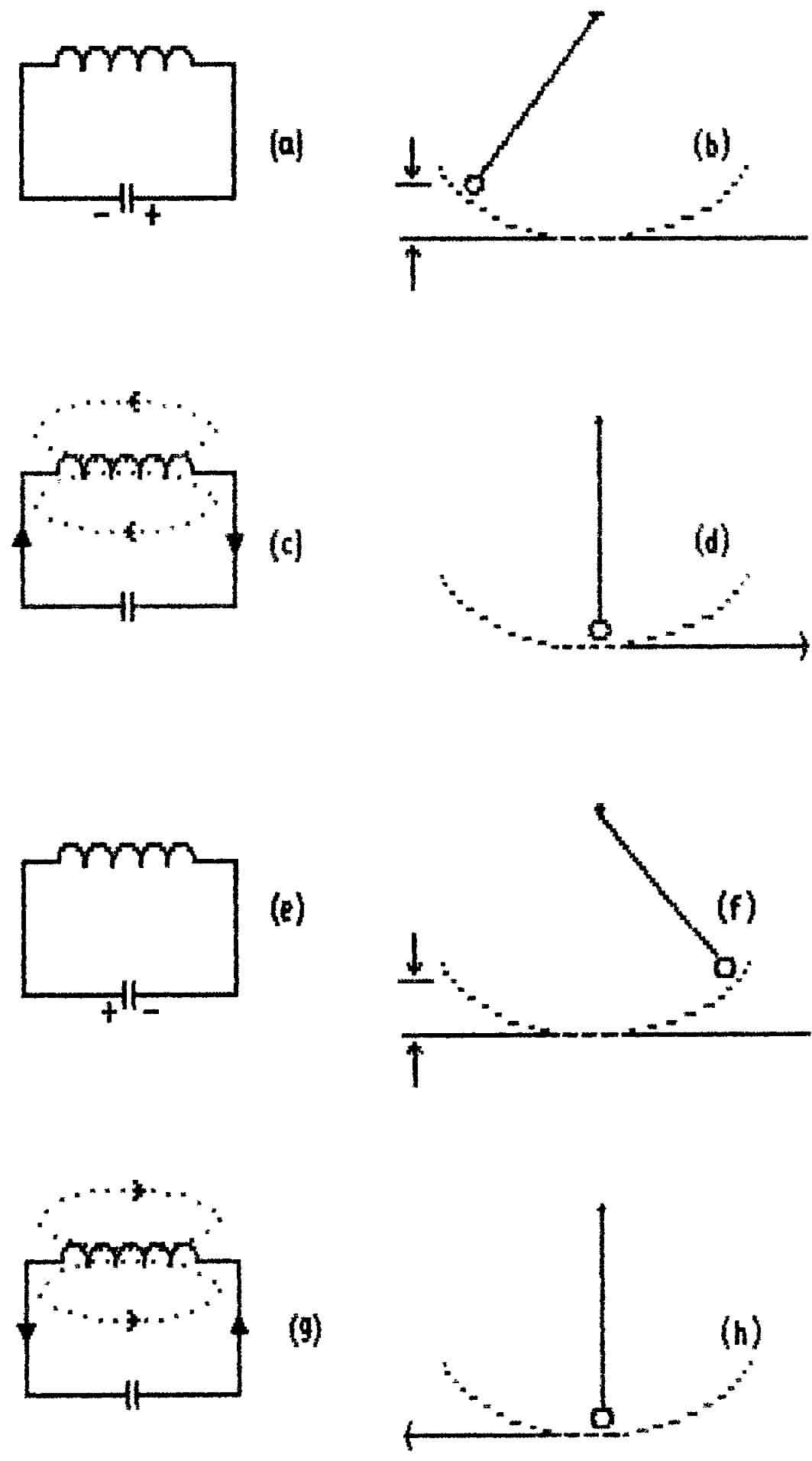
Fig.23 Comparison of Pendulum and Resonant Circuit |
d the current-flow has created a magnetic field ; see diagram (c). In
diagram (f) the pendulum is shown to have swung beyond the starting position
and to have climbed to a second position of potential energy-storage. By
virtue of its mass and velocity it has, like the child's swing, been reluctant
to stop at the bottom of its fall and has imitated the flywheel-like action
of the inductor. This reluctance to stop is referred to as momentum.
Diagram (e) shows the equivalent condition in the electrical circuit where the
capacitor is fully charged with reversed polarity. Diagrams (g and
(h) complete the cycle of action.
The similarity between the electrical circuit
and the mechanical pendulum is very real and it is common practice to solve
mechanical design problems by drawing an equivalent electrical circuit in which
inductors, capacitors and resistors represent mechanical parameters such as
mass, compliance and loss. The problems involved in the design say of
a loudspeaker can thus be solved using standard ac theory.
** That the resonance frequency is the
frequency at which things happen most easily can be deduced by inspecting
the impedance expressions derived in the previous Section. It
was said that inductive reactance is written as ωL and capacitive
reactance as -1/ωC ; in any circuit which involves both kinds
of reactance there results the combination
ωL - 1/ωC (or XL
- Xc).
Figs. 17 & 19 show
that XL increases with frequency
while XC decreases; there has to be a point where
the two curves intersect thus showing that, at that (resonance)
frequency, the reactances have the same value and so cancel. At this
frequency therefore the value of the current is determined only by
the circuit resistance.
Fig. 22 showed
a practical inductor and a practical capacitor connected together.
The two resistors RL and Rc represent the losses of the
two components which consist mainly of so-called ohmic
losses that arise from the passage of current through
their dc- resistance. In practice the losses associated with
capacitors are low relative to those of inductors (it is said that
the capacitor-losses are swamped by the inductor-
losses) and it is legitimate either to ignore Rc or to combine it with RL. This
leads to the more practical representation of Fig. 24(a). |
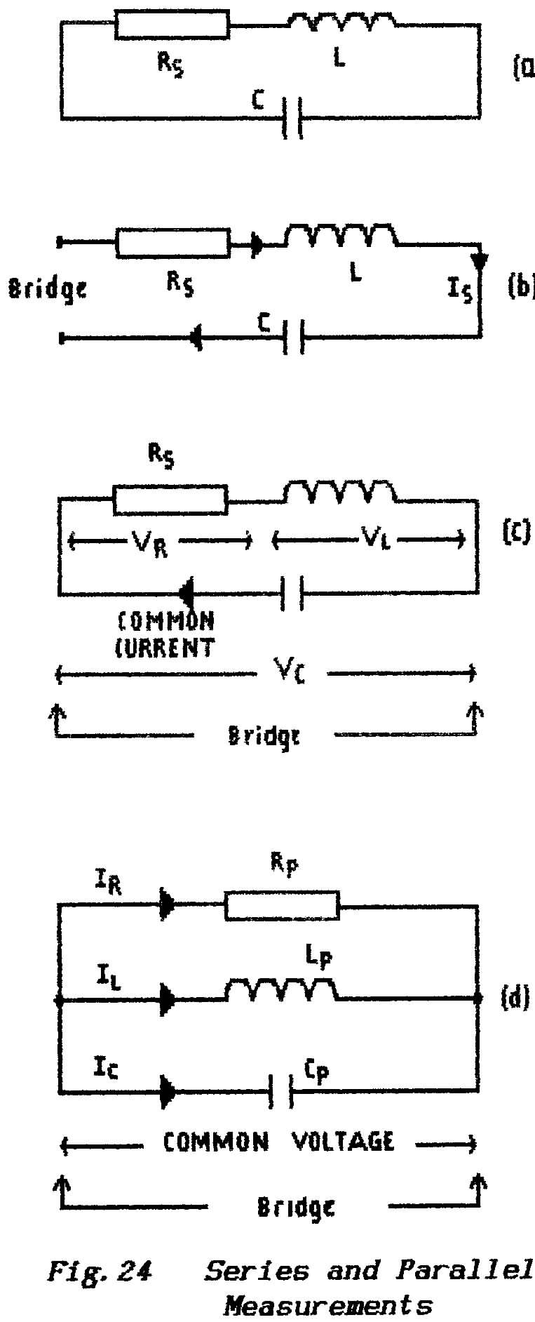 |
** Impedance is measured with an instrument called a Bridge which,
being without intelligence, has to be instructed as to whether the load presented
to it is a series combination of components or a parallel combination. Fig.24(b) shows
the arrangement of diagram (a) broken open so that measurements can be made
as a series circuit ; note particularly that a common-current flows through
all three components and also through the Bridge.
** In Fig.24(c) the LCR circuit is left closed and
the Bridge has been connected across the parallel combination of inductor and
capacitor; in fact the load presented to the Bridge is the combination
of a capacitor in parallel with a series combination of pure inductor and pure
resistance. Note that, in this arrangement, there is a common-voltage developed
across the capacitor, across the practical inductor and across the Bridge; the
currents that flow through the capacitor, the inductor and the Bridge are all
different.
There is a difficulty here; in diagram
(b) the Bridge is clearly presented with a series combination of L, C and R
but in diagram (c) it is presented with a mixture of series and parallel components. If
told that arrangement (c) was a parallel circuit the Bridge would interpret
its measurement results in the form shown in diagram (d).
The fact that both diagram (b) and diagram
(d) can represent the same combination of components is a bit startling but
it is a most useful result. To convert from one to the other form is a straightforward
mathematical process known as a series-parallel transformation but
it is not required for the R.A.E. A point to remember however is
that such transformations are valid only for the particular frequency
for which they were calculated.
Both Rs in the series arrangement and Rp in the parallel arrangement represent
the circuit losses which means that, whatever their calculated or measured
values, they must dissipate equal powers. They differ in that Rs carries
the common-current - the circulating current - that
circulates between inductor and capacitor while Rp has its own private current
which is driven by an emf that is common to itself, the inductor and the capacitor.
** The circulating current is controlled by the small-value Rs and so a large
current can be expected. This large circulating current must set-up large
p.d.'s across the reactors but, because the reactances cancel (i.e. the
voltage waveforms cancel), it is only the applied emf that appears across the
series resistor.
** When the circuit is measured as a parallel combination the very
large p.d. across the L and C becomes apparent but the overall current (the make-up
current) is small because cancellation now occurs between the
currents which flow through the inductor and the capacitor.
** Thus a series measurement shows the losses as a large resistive current
with a small voltage which requires a low-value resistor. A parallel measurement
shows the losses as a small resistive current with a large voltage which requires
a high-value resistor.
When measurements are made as shown in diagram (b) an LCR circuit is referred
to as a series-resonant circuit; when measurements
are made as shown in diagram (d) an LCR circuit is referred to as a parallel-resonant
circuit. The two
"arrangements" are essentially the same circuit but in their applications
they are very different.
1.13.2 The Series-resonant Circuit
When an LC resonant circuit is used in the
series mode the alternating circulating current is determined according to
Ohm's Law by the applied emf and the overall impedance at that particular
frequency.
In the general form this is given by
I = E/Z = E/(R + XL
- XC)
At the resonance frequency, where the inductive
reactance equals the capacitive reactance, this reduces to E/R.
When the frequency is reduced below the resonance frequency the capacitive
reactance Xc is increased but the inductive reactance XL is reduced
and so the two reactances no longer cancel. Similarly if the frequency
is increased above the resonance frequency the capacitive reactance decreases
but the inductive reactance increases; it is only at the frequency of
resonance that complete cancellation is possible.
** Fig.25 is a graph on which is re-plotted
the inductive and capacitive reactance curves of Figs. 17 & 19 together
with a curve that represents the difference (XL - Xc:). This shows
that the impedance is reduced to Rs alone at resonance with the curve
rising toward the capacitive-reactance curve at lower frequencies and toward
the inductive-reactance curve at higher frequencies.
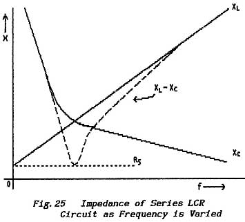 |
** Because, at resonance, the series impedance falls
to its lowest value then the circulating current must reach its highest
value; as already discussed the p.d. developed across each reactor
must also reach its maximum value. Note that the impedance curve is not
symmetrical because the two reactance curves have different forms.
Although at resonance the series circuit
appears to be purely resistive and to present its lowest impedance
it is important to remember that nevertheless it does contain reactors
and that there is a relatively large voltage across each of them. If
the given inductor and capacitor are removed from the circuit and replaced
by components of the same value but of higher quality (i.e. with lower
losses) then the value of the equivalent resistor Rs. is reduced and
so the circulating current is increased ; in turn this
leads to an even higher p.d. developing across the reactors. With
components of even reasonable quality these voltages can be 10-times
the value of the applied emf and are often much greater. |
WARNING When dealing with transmitters these voltages can
be lethal.
** This voltage-multiplication action is one of the most useful
properties of resonant circuits. If an applied Source delivers
a mixture of signals at different frequencies (as does a receiving aerial)
then that signal whose frequency is closest to the resonance frequency develops
a much larger voltage across both the inductor and the capacitor than do the
other signals. This provides a means of selecting a wanted signal from amongst
many. The action of adjusting a circuit so that its resonance frequency equals
the frequency of a wanted signal is known as tuning the
circuit to that signal and so these resonant circuits have acquired the name tuned
circuits.
** A practical arrangement which enables a wanted signal to be selectively
enhanced before being passed to a receiver is shown in Fig.26(a) ; the
arrow drawn through the capacitor symbol indicates that the component can be
adjusted mechanically to provide a means of tuning the circuit. Similar tuning
arrangements can be provided by varying the inductor but, as a general rule,
it is less easy and more expensive to achieve than the variable
capacitor.
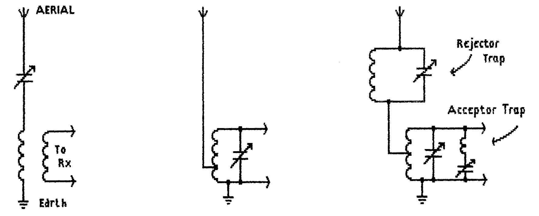
Fig. 26 Use of Resonant Circuits In
Aerial Arrangements
(a) series-tuned Aerial Transformer
(b) parallel-tuned Aerial Transformer
(c)
Rejector and Acceptor Traps or Notch Filters
Note that, although the wanted signal is magnified relative to unwanted signals,
this is not an example of amplification; that term implies an increase
in signal power and requires the use of an auxiliary
power source.
The degree of magnification obtained is determined
by the current-flow at resonance compared with the current-flow at off-resonance
frequencies. The current-flow at resonance is controlled by the circuit resistance, the
current-flow below the resonance frequency is controlled by the capacitive
reactance and the current-flow above the resonance frequency is controlled
by the inductive reactance.
** Signal magnification therefore depends on the ratio of reactance
to resistance and this was the criterion used to define the quality (the Q-value) of
a reactor. Thus the performance of tuned circuits is also given in terms of
Q.
In general the losses connected with capacitors
are negligibly small and so the magnification of a resonant circuit is usually
taken as the Q-value of the inductor. For example:
a resonant circuit which contains an inductor with a Q of 10 would be expected
to provide a signal magnification of 10 times at the resonance frequency. In
most practical circuits a Q of 10 is about the lowest likely to be acceptable
although, in the final stages of a transmitter, the output circuit may have
a Q as low as 2 because it is required to be "lossy" - it is required to
lose its power to the aerial
A very important point which has implications
in receiver design and also in oscillator circuits arises from the tuning arrangements
outlined above. Suppose for example that it is required to raise the resonance
frequency of a tuned circuit; the value of the capacitor is decreased
so that its reactance at the new frequency will equal the higher reactance
of the inductor at that new frequency and this adjustment will not appreciably
alter the value of the circuit losses Rs.
However, because the reactances have increased while the value of Rs is unchanged,
the circuit Q-factor has been increased.
** This means that the magnification of a variable tuned-circuit
varies as its resonance-frequency is adjusted.
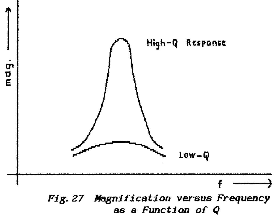 |
** An effect of much greater importance however
is shown in Fig.27 where the magnification
of resonant circuits is shown as it varies with changes of frequency.
At low values of Q E the magnification is almost independent of frequency
and we say that the selectivity of the circuit
is low. At high Q-values the magnification peaks significantly
at the resonance frequency and such circuits
are said to offer high selectivity.
** If the Q-value
of adjustable circuits varies with frequency then clearly the magnification
also varies with frequency and this is a serious handicap for equipment
which is required to operate over a band of frequencies. For
this reason the simple arrangement of Fig.26(a) is
seldom found by itself ; see under Bandwidth in
the next Section and also in the Lessons dealing with Receivers. |
** Series-tuned circuits are characterised by a large flow of current
at the resonance frequency and they are regarded as being willing to accept
signals at that frequency while rejecting all others.
From this they have acquired the name Acceptor Circuits . Their
stock-in-trade is a reduction of impedance at resonance.
END OF LESSON 9
* * * * * * *
* * * * *
QUESTIONS
1. What particular characteristic of a reactive circuit indicates that it
is operating at its resonance frequency ?
2. Explain in simple terms the difference between a so-called series-resonant
circuit (or Acceptor circuit) and a so-called parallel-resonant circuit (or
Rejector circuit).
3. At what frequency will a 2 μH choke resonate with stray capacitances
measured as 10 pF ? See Lesson-8. (This question tests
your ability to work with powers of 10 and is the type that can earn easy marks
in the exam.
If you have problems then please ask for help.)
4. Why are very large voltages present in tuned circuits which are handling
power (such as the final stages of a transmitter) ?
5. What is the basic purpose of an aerial transformer as used in a receiver?
6. Why is a simple tuned-circuit arrangement not very satisfactory in equipment
which is required to operate over a fairly large band of
frequencies ?
Back to Top of Page
LESSON 10
1.13.3 The Parallel-resonant Circuit
An alternative way of measuring a resonant circuit
is simply to connect a Bridge across the combination of components as shown
in Fig.24 (c). From the measurement point of view
the Inductor, the Capacitor and the (theoretical) Resistor are now seen as
being connected in parallel as shown in Fig.22(d).
** When a bridge is connected in this manner it is no longer
possible to determine the common circulating current and only the common voltage
across the components can be measured. To the Bridge the capacitive and
inductive currents now flow in parallel and, as already discussed, they cancel
(exactly at the resonance frequency). Thus the bridge measures
a relatively small current which is known as the make-up current ;
this represents the losses in the circuit.
** In the series circuit discussed in the previous Section there
is a common current and the two reactive voltages differ;
in this parallel circuit there is a common voltage and it is the two reactive
currents that differ. As the frequency of resonance is approached so
the current-canceling action becomes total and the make-up current consists
of that which flows through the resistor alone. Hence, in this circuit,
resonance is indicated by a minimum value of current
which is interpreted as a maximum value of impedance.
** Where the series circuit accepts signals at or close to the
resonance frequency, this parallel circuit rejects such signals and is accordingly
known as a Rejector Circuit.
** Remember however that, although the bridge cannot measure the current
which circulates between the Inductor and Capacitor, that current nevertheless
still flows and it still reaches it maximum value (controlled by the effective
series resistance) at the resonance frequency. Thus the parallel circuit rejects
current at resonance but develops a magnified voltage at that frequency. The
use of such a circuit in selecting a wanted signal from an aerial is shown
in Fig.26 (b).
** The impedance presented by an aerial may be relatively-low
or extremely reactive so that it either reduces the Q of the tuned-circuit
or de-tunes it. This effect is off-set by using the tuned inductor as
an autotransformer (see Lesson-5)
and so the two arrangements of Fig.26 (a & b) are
perhaps less different than it may appear.
** Fig.26 (C) shows another
use for both acceptor and rejector circuits ; here they are used as traps
to reduce the passage of powerful unwanted signals. A rejector connected in
series with the aerial feed reduces the level of signals at or close to the
frequency to which it is tuned ; an acceptor connected across the terminals
which feed the receiver tends to short-circuit signals at or close to the frequency
to which it is tuned.
Because these circuit arrangements result in
a
"hole" in the range of receivable frequencies they are also called notch
filters.
** The two different methods of measuring resonant circuits in fact
result in slightly different resonance frequencies and reference books will
be found to give different formulae. In practice however when dealing
with circuits of
reasonable Q-value the difference is negligible and for all practical purposes
the standard formula, as already given, is
f = 1/(2π.√(LC)
where f is in Hertz, C is in Farads, L is in Henrys.
1.13.4 Dynamic Impedance
Where say a rejector circuit is to be used to
develop a signal voltage at a preferred frequency it is helpful to the Designer
to know exactly what impedance it will present ; off-resonance that impedance
will be a mixture of resistance with either inductive or capacitive reactance
depending on the direction in which the circuit is off-tune.
The impedance thus presented by a rejector
circuit at resonance is known as its dynamic impedance; at
resonance the impedance should be exactly resistive and so is sometimes referred
to as the dynamic resistance.
With the application of Ohm's Law the dynamic
impedance is obtained by dividing the applied voltage by the make-up current
which, in turn, depends on the Q-factor. A low Q implies that the components
are lossy and that perfect cancellation between the reactive currents is not
possible; in turn this means that the make-up current is not small
and so the dynamic impedance is low.
With similar reasoning a high-Q circuit presents
a large dynamic impedance.
As already discussed the Q of a resonant circuit
varies with
(a) frequency - because the ratio of resistance to reactance
changes
(b) the value chosen for the inductor/capacitor (L/C) ratio combination
because this too changes the ratio of resistance to reactance ; the
resonance frequency is determined by the product L x C.
Thus the value of the dynamic resistance can be controlled by the Designer
because he is free to choose the combination of
L and C to suit the value of resistance that is imposed by the circuit losses.
He is also faced with a compromise decision because the ratio X/R
determines the circuit Q which controls the band of frequencies over which
the tuned circuit operates.
This matter is usually dealt with in a somewhat
rule-of-thumb manner by considering the ratio of inductance to capacitance
(i.e. L/C) which is called the L-C Ratio ;
a high L/C ratio results in a high dynamic resistance.
See also the later Sections on Bandwidth, Bandpass
Circuits, Amplifiers, Oscillators, Receivers and Transmitters.
1.14 BANDWIDTH
1.14.1 Definitions
** The term bandwidth refers to the band
of frequencies over which a particular piece of equipment will operate satisfactorily. Bandwidth
is limited by a number of factors:
(1.) At the lower end of the frequency range performance deteriorates
because of the increasing attenuation of coupling circuits; see Fig.
28.
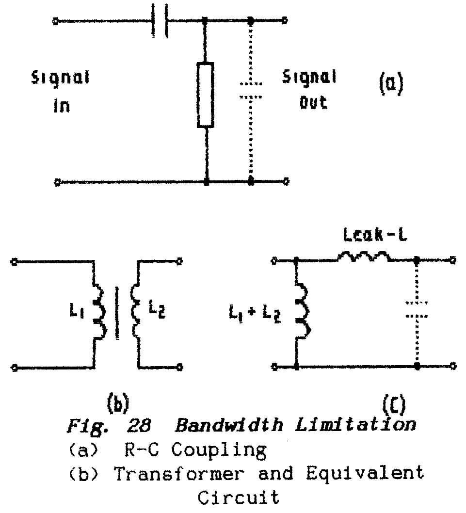 |
** The coupling capacitor in Fig.
28(a) is inserted to separate an ac signal from dc
with which it is mixed but at low frequencies the rising reactance
of the capacitor reduces the wanted signal also.
** In Fig.28(b) a transformer
is used to separate the wanted signal from a dc. However the
transformer windings appear as Inductances connected across the signal
path and, as the frequency decreases, so the falling reactance diverts
signal current away from the intended destination.
** (ii) Another cause of loss at low
frequencies is the increase of feedback through the failure of by-pass
capacitors (see Part 2 Electronic Amplifiers.
(iii) At the high end of the frequency range
stray capacitances, shown in Fig. 28(a) in
broken line, provide increasingly-effective alternative paths for signal
currents which therefore fail to reach their intended destination as
the frequency increases.
** (iv) In designing transformers it
is very difficult to ensure that all the magnetic field from one winding
interacts with the other winding and this "lost" magnetic
coupling is referred to as leakage inductance. As
shown in the equivalent circuit (C) leakage inductance appears as an
inductive reactance in series with the signal path and this limits
the high-frequency response.
** (v) In tuned (radio-frequency)
amplifiers the bandwidth is determined solely by the characteristics
of their resonant circuits ; see under 2.6 and under 1.
13 in the previous Lesson. |
Bandwidth however, expressed as a lower-to-upper frequency range, can be a
deceptive quantity. For example:
an audio amplifier ranges from
50 to 15,000 Hz
a video (television) amplifier ranges from
0 to 5MHz
a radio-frequency amplifier might range from 100 to 120 MHz
In the order shown the bandwidths may appear to increase from 15 kHz to
20 MHz yet the difficult tasks are to extend the bandwidths of the audio amplifier
and to restrict the bandwidth of the rf amplifier.
** Another way of expressing bandwidth is to give the upper and lower limits
as variations on the centre frequency. Thus the rf amplifier, which has
a centre frequency of 110-MHz and extends both upward and downward by 10 MHz, can
be described as having a bandwidth of 110 ± 10 MHz. Alternatively
this amplifier is said to have a relative bandwidth of
(approximately) 9% which shows the frequency range as a fraction of the centre
(or average) frequency.
** Again there is a difficulty in that at 1 MHz a relative bandwidth of 10%
is only 100 kHz which is at variance with the same relative bandwidth at 100
MHz.
Clearly, as the centre frequency is increased, so it becomes ever more difficult
to restrict the relative bandwidth.
As a description of performance in audio and
video amplifiers the term relative bandwidth becomes
something of a joke. For example, the video amplifier would be said to cover
a range 2.5 ± 2.5 MHz ;
expressed as relative bandwidth this becomes +100% - ??% .
Where, as in video amplifiers, the bandwidth
approaches zero frequency (or dc) then bandwidth is described in terms of the
number of octaves covered. Mathematically an octave describes
a frequency interval in which the upper limit is twice the lower frequency-limit; to
the Human ear an octave is not exactly 2:1. For the above audio amplifier
the bandwidth is approximately 8 octaves; for the video amplifier the
practical bandwidth is about 17 octaves; for the rf amplifier the bandwidth
is about 0.2 octaves.
This method of expressing bandwidth makes clear the difficulty of extending
the range of audio and video equipment and of compressing the range of rf amplifiers.
Apart from the limitations described above
all three methods are valid and the choice is governed by the particular requirements
of the moment.
It must always be remembered however that a
given bandwidth is purely a matter of definitions because electronic equipment
does not suddenly cut-off at the edges of the band. For amplifiers
it is usual to define the band as the range between those frequencies where
the gain has dropped to 0.7 of the maximum gain (known as the 3-dB points). For
aerials the bandwidth is usually defined in terms of the standing-wave
ratio (see under 2. 3: Transmission Lines)
which is a measure of the accuracy to which an aerial system is tuned and matched.
1.14.2 The Significance of Bandwidth
** The sinewave (see Trigonometry in Part
7 : Mathematics) is the simplest, indeed the purist, of repetitive
waveforms. All waveforms which repeat can be broken down into a series
of sinewaves which are harmonically-related to the repetition frequency
(or frequencies). The repetition frequency is called the first harmonic
or the Fundamental, the frequency which is twice that of the Fundamental
is called the second harmonic, the frequency which is three times that
of the Fundamental is called the third harmonic and so on.
For any one specific repetitive waveform each harmonic has a specific amplitude
and a specific phase relative to the Fundamental.
The process of deriving these component sinewaves
from a given repeating waveform is known as Fourier Analysis after
the French mathematician who first derived it but knowledge of this is not
required for the R.A.E.
** It is the presence of these extra frequencies that makes it
necessary to consider bandwidth in the performance of any equipment. In
general the ear is not fussy about phase relationships and so, in audio-amplifier
design, phase-distortion (disturbance of phase relations) is not directly
of concern; the important thing is to preserve the relative amplitudes
if the original sound is to be reproduced faithfully. However, when feedback
is used in an amplifier, phase-distortion must be controlled else negative-feedback
turns into positive-feedback with unfortunate results. (Note that the amplifier
must be well designed before feedback can be applied.
The eye is not so accommodating and, in video
amplifiers, it is essential to preserve both the amplitude and phase relations.
** In general rapid phase shifts are associated with rapid changes
of gain as frequency is varied and a design which eliminates too-rapid changes
of gain at the edges of the pass-band should not suffer problems from phase-distortion,
** In communications engineering, and especially applicable to Radio
Amateur working, bandwidth is an important consideration in limiting interference
which a transmitter may cause to other installations. A signal which varies
its amplitude slowly and only by small amounts generates few harmonics and
they have relatively small amplitudes; a signal which varies rapidly
and by an appreciable amount generates a large number of large-amplitude harmonics.
** In particular those signals which change amplitude abruptly
contain high-order harmonics which can have very large amplitudes and intrude
into a large slice of the frequency spectrum. Thus to keep interference
to a minimum - to restrict the frequency-band over which the signal spreads
- the basic requirement is to ensure that signals do riot change too rapidly.
** Of course, when transmitting in Morse code, it is not possible
to either close or open a key slowly; when speaking into a microphone
it is not possible to avoid those sharp explosive sounds (expletives) which
cause transients. These matters are dealt with electronically by "restricting
the bandwidth"; when high-order harmonics are removed then
sharp-edged waveforms become softened.
** For W/T working it is mandatory to fit so-called key-click filters
which prevent a too-rapid change between transmitter-on and transmitter- off. For
R/T working the audio amplifier must be suitably restricted in its bandwidth
to ensure that it neither passes nor produces those high-order harmonics. See
also under 4.2.5 Low-pass Filters.
1.14.3 Bandpass Arrangements
In radio-frequency amplifiers tuned circuits
are used as impedances and these have a bandwidth which is determined by the
circuit Q-factor ; see under 1.13, 4.2 and 4.6 . High-Q
circuits are relatively loss-free and produce high dynamic impedances but they
restrict the bandwidth. Low-Q
circuits are lossy and produce low dynamic impedances but they offer wide
bandwidths.
Apart from the obvious compromise required
there is a further complication mentioned under 1. 13. 2 that
the circuit Q - and therefore the bandwidth - varies as tuning adjustments
are made. One expensive cure for this problem is to arrange that the
tuning control varies simultaneously both the capacitor and the inductor. If
the trick is made to work then the LC product is varied to change the frequency
while the L/C ratio is varied to correct the bandwidth and/or the dynamic impedance.
A cheaper method is to use so-called bandpass
circuits; see under 2.7.3 . Basically
there are two types;
In the first of these the signal is passed
through a succession of resonant circuits whose resonance frequencies are staggered
across the required band. The alignment of such circuits is not easy but they
can offer a substantially constant response and they are relatively independent
of Q-values. Because most of the tuned circuits are not operating
at their resonance frequencies, and therefore not providing their maximum magnification,
the signal suffers attenuation as it passes through. These are known
as stagger-tuned circuits.
The second type is the bandpass-coupled circuit
in which two or more resonant circuits, each tuned to the centre frequency
of the required band, are coupled together. The coupling may be
magnetic (transformer) or via a common impedance which can be either inductive,
capacitive or a combination of both. A common-resistor coupling
is possible but this lowers the Q.
In these circuits not only is energy circulated between the capacitor and
inductor of each resonant circuit but it is also interchanged between the coupled
circuits. The effect is to produce a constant response over the required bandwidth
but, with each circuit providing maximum magnification, the signal suffers
less attenuation. The Q-values of the resonant circuits must be well
matched.
Circuit Q-values are dependent on circuit losses
and these are not easily predicted; it is usual to design the resonant
circuits with too-high a Q and to add damping resistors as necessary.
Although bandpass circuits produce a substantially-constant
response over a band of frequencies the price exacted is that the response
falls rapidly at the edges of the band. The resultant phase-distortion could
cause problems but these steep skirts in the response curve is a desirable
feature in receivers where they effectively remove unwanted signals.
** The nature of bandpass circuits means that they are only
really practical for fixed-frequency working; to make them tunable over
any useful range requires constant control of Q, dynamic impedance, bandwidth
and coupling factors. The problem is overcome in radio receivers by using the superheterodyne
principle; in such receivers the majority of the circuit
operates at a fixed frequency (known as the Intermediate Frequency or IF)
and any wanted incoming signal is converted to that frequency in a frequency-changer
stage. See also under 2. 7 and 4.6.
END OF LESSON 10
* * * * * * *
* * * * *
QUESTIONS
1. An Inductor and a Capacitor are connected together. Say briefly why this
arrangement is often considered as two different circuits ?/p>
2. Why and when would you beware of dangerously high voltages in such an arrangement?
3. There is a requirement for a trap to attenuate a signal at a frequency
of 1-MHz in a circuit which operates at an impedance of 1,000 ohms. Two
combinations of L and C are given below both of which resonate at (approx)
1 MHz ; state which you would choose to form a high-Q trap.
(a) 0.003 μF and 8 μH each offer 50 ohms at 1-MHz
(b) 5 pF and 5 mH each offer 30,000 ohms at 1-MHz.
Give the Q-factor you would expect to achieve.
(Think carefully about this one - you are unlikely to meet this
in the R.A.E.)
4. What is the purpose of a notch filter ? 5. What
problems arise from attempts to make a resonant circuit adjustable to a range
of resonance frequencies ?
6. A transmitter and receiver are required to operate at the Amateur frequency
of 3.66 MHz using Morse code. Why must both pieces of equipment have a bandwidth
that will accommodate more than just the keyed carrier on 3.66 MHz ? 7. Why must
the bandwidth of equipment be limited to just that range which is required for
its specific purpose
8. Constant performance over a given bandwidth is achieved by use of bandpass circuits.
What are the major advantages and disadvantages of using either stagger-tuning
or coupled circuits ? (Not for R. A. E.)
9. Variable-tuning circuits are a particular disadvantage in receiver design.
How is this problem overcome?
Back to Top of Page
LESSON 11
1.15 INTERNAL RESISTANCE
1.15.1 Introduction
Under 1.3.3. in Lesson-1 it
was shown that a generator cannot deliver current until its terminal voltage
has fallen because current cannot flow between points of equal potential; the
terminal voltage falls according to the current-demand. This phenomenon introduces
a problem because the current that will flow through a given load depends on
the value of the terminal voltage while that voltage itself depends on the
current-flow.
** The solution to this problem is elegant and yet absurd. A
circuit is invented which behaves in exactly the same manner as the practical generator
but which uses only a theoretically-perfect generator. Such a circuit
(which cannot possibly exist in practice) is known as an equivalent circuit. The
generator used in this equivalent circuit is theoretically untroubled by problems
of internal equilibrium and so its terminal voltage does not fall when current
is demanded. To form the equivalent circuit the theoretical generator
is degraded (i.e. made normal) by adding theoretical losses until the performance
of the combination matches that of the practical generator.
The idea of the perfect generator causes the problem to split into two separate
solutions which, in fact, are but two ways of looking at the same phenomenon. Either
the perfect generator can be made to supply any required current without
its terminal voltage changing or it can be made to supply any required voltage
without the current changing. It cannot be asked to keep both parameters
constant because that would severely limit the usefulness of the generator.
Perfect generators of the first type are called constant-voltage
generators (or cv-generators) and the second type are called constant-current generators
(or cc-generators)
1.15.2 The Constant-voltage Generator
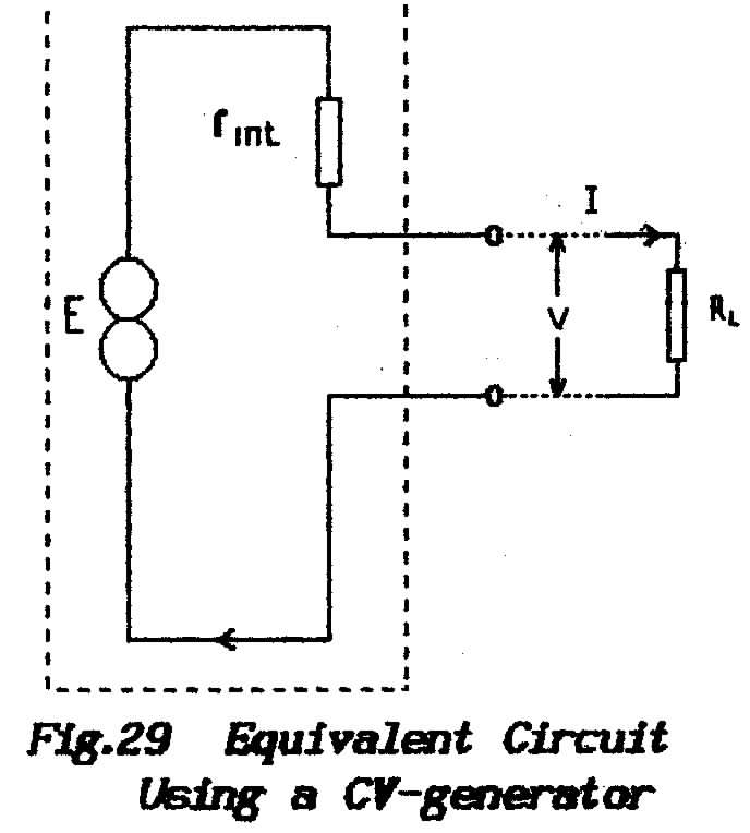 |
Fig.29 shows
a cv-generator (note the symbol) connected through a resistor labeled rint to the output terminals of a practical generator; a load resistor
RL is shown connected externally. The resistor rint which is shown "inside" the generator is always known as
the internal resistance of the practical
generator.
Without the connected
load the supplied current I must be zero and so the p.d. developed
across rint must be zero also. Under
no-load conditions therefore the voltage at the terminals of the practical
generator is that of the constant-voltage generator. This voltage is
referred to as the emf (electromotive force) of
the practical generator and is given the symbol E. The symbol V is
reserved for the terminal voltage of a generator when current is flowing
and also for the p.d. developed across a load (caused by the transfer
of electrons). |
The purpose of the resistor rint in the equivalent circuit is to ensure that, as current is demanded, so the
terminal voltage (of the equivalent circuit) falls in imitation of the terminal
voltage of the practical generator which it represents.
** The only way to assign a value to rint is
to measure it experimentally; the values of V are noted for different
values of current-flow when the value of rint can
be found using Ohm's Law as
rint
= change of V
change
of I
** The value of E can be measured at the terminals with zero load
current thus, once the value of rint has been measured,
it is possible to calculate the current for any given value of load resistor
(RL) from the equation
E = I x (RL + rint)
(the current multiplied by the total resistance around the circuit).
** Once the value of I has been determined it is possible to calculate
the p.d. across the internal-resistance; the terminal voltage is then
found by subtracting that p.d. from the emf E. Alternatively
the value of V can be found directly by multiplying RL x I .
** Yet again the two resistors RL and rint
form a potential divider across the emf; part
of the total voltage appears across rint and the remainder
appears across RL.
From this it is an exercise in fractions to deduce the voltage across the load
V =
E x RL/(RL + rint)
** For generators which produce ac the internal resistance becomes
the internal impedance which has the complex form (rint
+ jXint); see Lesson-8. It
is important to remember that, although the effect of internal resistance is
real enough, its existence is pure fiction - a mathematical convenience.
For active systems such as amplifiers rint may be referred
to as the output impedance or as the source
impedance of the system.
(The same idea in reverse leads to the concept
of input impedance which describes the current which
flows into a device as a result of applying a given input voltage.)
In separating the cv-generator from the failings
of the real generator it has been stipulated that the cv-generator shall have
an internal-resistance of zero; this is the reason its terminal
voltage does not fall under load. It is this aspect of the equivalent
circuit which is absurd. The Maximum Power-transfer Theorem states that
a generator delivers maximum power into a load which exactly matches its internal
impedance; this cv-generator therefore must
deliver its maximum power into a short-circuit (zero ohms) and zero output
power does not make it an ideal power source. Nevertheless the trick
provides a legitimate way to calculate the performance of circuits and that
is a prerequisite for design work.
Consider again the equality above in which
the e.m.f. is equated with the product I x (RL + Rint) ; in
mathematicians' language we say that, if the value of rint is
small compared with the value of the load, then rint can be neglected . In
that event the terminal voltage does not fall when current flows. We
say that rint is swamped by the load; it
has negligible effect on the current.
In practice therefore, as long as a load is
considerably greater than the internal resistance of the generator, then the
generator tends to behave as though it were a perfect constant-voltage generator
(zero internal impedance). This is an important consideration in
circuits where it is required to maintain an undistorted voltage-waveform ; before
pursuing the matter further however it is best to consider the alternative
equivalent circuit which arises when the internal-resistance is the greater
and the load becomes negligible.
1.15.3 The Constant-current Generator
Fig. 30 shows
a cc-generator (again note the symbol) which is connected directly to the output
terminals of the practical generator which it represents. Be reminded
that this theoretical generator produces an unvarying current without the intervention
of an emf.
For the internal resistance to be much larger than any load
it must have an infinitely-large value. But an infinitely-large value means
that rint is not there and the generator would be required
to produce an output when it is not connected to the load.
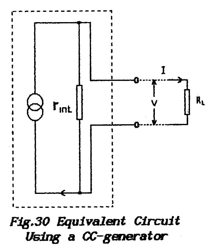 |
** The solution (in this theoretical circuit) is
to place the internal resistor across the
generator ; its function now is to absorb, or to divert, any
of the constant-current that the load cannot accept. This perhaps odd
arrangement is perfectly legitimate because we are trying to invent
an equivalent circuit that will exactly imitate the behaviour of the
real circuit.
In this equivalent circuit the distinction
between E and V is meaningless because this theoretical generator produces
a current (as distinct from producing an emf) . The current from the
generator (I) divides according to the relative impedances of the two
available paths.
Using the parallel version of Ohm's
Law the load current IL is this total current I multiplied by rint/
RL + rint) . If RL is negligible then all the current
is flowing through the load.
The voltage that is developed across the Load is the product
I x RL |
In practice as long as the internal resistance
is much larger than the load then the generator tends to behave as though it
were a perfect constant-current device with infinite internal impedance.
This is an important consideration in circuits where it is required to maintain
an undistorted current waveform.
The concept of a cc-generator is in fact as absurd as the cv-generator as
can be seen by again referring to the Maximum Power-transfer Theorem. This
generator must deliver its maximum power into a load that is not there but
again it provides a means of performing circuit calculations.
1.15.4 Voltage and Current Sources
Any practical generator
behaves either as a cv device or as a cc device determined by the circuit into
which it is driving. A signal source is referred to as a voltage
source if its operation tends to that of a cv- generator because its output
impedance is low in comparison with the load when variations in the load impedance
do not affect the voltage waveform.
The same signal source would be referred to
as a current source if its operation tended to that of a cc-generator because
its output impedance was high in comparison with the load ; variations
in the load impedance would not affect the current waveform.
A practical application of this is shown in Fig.
31 where a variable resistor is connected as a pot'meter to
vary the drive to an amplifier stage.
Behaviour of a valve is determined by the voltage-waveform
which is impressed between its grid and cathode but the similar behaviour of
a (bipolar) transistor is determined by the current which is injected into
its base-emitter path.
Diagram (a) shows that the input to a valve has the nature of a capacitor
and the reactance of this reduces as the frequency is increased. To avoid distorting
the voltage waveform at the grid of the valve it is imperative that it be driven
from a source whose internal impedance is low relative to the overall impedance
between grid and cathode. The gain control must therefore be a potential divider
which taps-off a portion of the applied voltage.
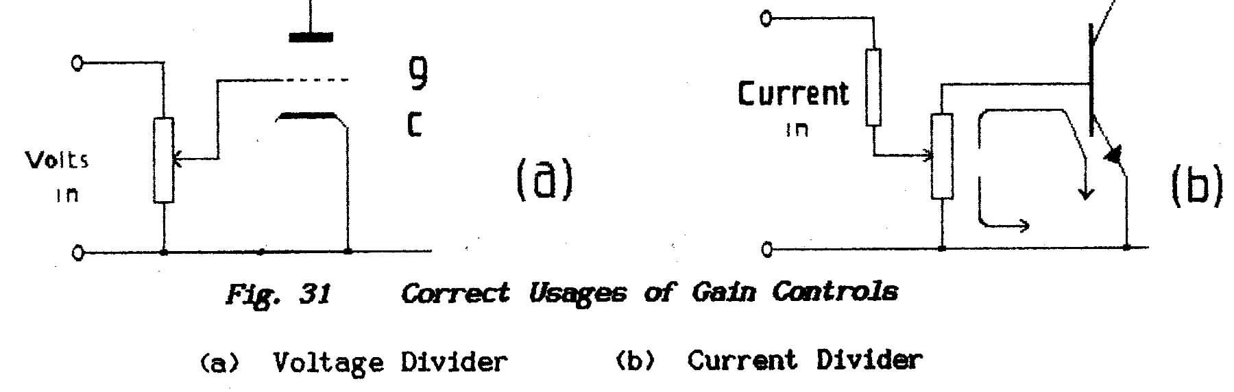
Diagram (b) shows that the input to a transistor
offers a dc path and so the device can be expected to draw current from the
source. What the diagram fails to show is that the resistance of the base-emitter
path depends on the magnitude of the applied signal-current and so the input
resistance varies in sympathy with the signal waveform. To avoid distorting
the current waveform between base and emitter it is imperative that the transistor
is driven from a source whose internal impedance is relatively high. The gain
control for this simple amplifier therefore must be a current divider.
As shown the signal is split between two alternative
paths and the pot'meter is connected as a differential control which
shunts unwanted signal away from the transistor. The series resistor
Rint is inserted as necessary to prevent the pot'meter short-circuiting
the source at minimum-gain setting.
The arrangement of (a) is sometimes seen controlling
a transistor stage and the error has two consequences:
(a) operation of the control to increase the gain causes the gain first to
rise and then to fall
(b) the transistor is driven from a source-impedance represented by the
lower half of the pot'meter ; consequently at low-gain settings
the drive is converted to cv operation and distortion ensues.
Note however that the application of feedback
to the transistor stage may convert it effectively to voltage-operation and
so use of arrangement (a) would be correct.
1.15.5 Practical Significance of Internal Impedance
The concept of internal impedance was introduced
to make it possible to perform circuit calculations. To demonstrate its
impact in the practical world consider a unit intended for test purposes which
is known as a Signal Generator (or S.G.) . This produces
a signal at a frequency which can be adjusted and also at a level which can
be adjusted accurately over a range of values.
From what has been said above it is clear that
the actual signal which the test equipment injects into a load must depend
on both the input-impedance of that load and the output-impedance of the S.G.
and this could make nonsense of any attempt to calibrate the output level of
the generator. In practical work all generators are considered as voltage
generators unless otherwise specified and so manufacturers state S.G. outputs
in terms of an emf and internal resistance.
For example it might be given as an emf of
1 volt at 50 ohms. Because an emf' is stated we know that,
connected to a 50-ohm resistor, this generator will provide an output of 0.5
volts when all the output attenuators are set for zero attenuation (maximum
output). It is a bit inconvenient to work relative to 0.5 volts
and so most S.G.'s are built with an emf of 2 volts.
Sometimes a generator may be quoted as "delivering
1-volt across 50 ohms"; this is a statement of terminal
voltage when the Instrument is correctly matched and so we can deduce that
it affords an emf of 2-volts with an Internal resistance of 50 ohms.
However not all equipment offers
an input impedance of 50 ohms and it is an expensive hobby to keep a flock
of S.G.'s to provide a range of output impedances. It is perfectly
legitimate to connect a 50-ohm generator to say the 75-ohm input of a receiver
- the Designer will have ensured that this does not affect the operation
of the device - but the Operator must re-calculate the voltages that will appear
across the receiver input-terminals. This is a simple matter ; go
back to the value of the emf, note the output impedance (rint ) and
call up the equation given above wherein
V = emf x RL/(RL
+ rint )
Once this value has been established for any convenient setting of the output-attenuator(s)
all other outputs are changed in the same ratio.
An alternative is to connect the S.G. to the
receiver via a matching pad which is a network of
resistors whose input resistance matches rint and
whose output resistance matches the input resistance of the receiver. Of
course allowance must be made for the attenuation caused by the pad which is
most easily done by directly measuring the voltage across 50-ohms without the
pad and the voltage developed across (say) 75-ohms with the pad.
1.15.6 The Constant-resistance Network
In the above discussion the internal impedance
of the S.G. has been assumed to be a pure resistance but the argument is not
in any way affected if that internal impedance is complex. Most definitely
however that is not true for a practical situation ; if the internal
impedance is not resistive it is imperative to know its exact value for all
possible output frequencies so that the true terminal voltage can be calculated. To
prepare a full calibration is not practicable.
Fortunately it is possible to make the output
impedance substantially resistive for all frequencies by adding corrective
components which turn the output circuit into a constant-resistance
network. The underlying mathematical derivation is
not required here but the circuit arrangement is shown in Fig.
32. For example, if the output is measured as an
inductor in series with a resistor, then that output circuit is shunted
with a capacitor in series with a resistor of the same value such that
L/C = R2
where L is in Henrys, C is in Farads and R is in Ohms. When this is
done correctly then the output impedance is resistive at all frequencies.

Such a correcting network is built into the
instrument which is why its rint can be quoted as (say)
50-ohms. (Note that the equation does not include a frequency term; i.e.
neither w nor 2πf appear
This same circuit trick is called upon to obviate the effects of reactances
where they become a nuisance. For example electrical equipment causes
radio interference because sparks are produced when an inductive circuit
is interrupted. When the device is incorporated into a suitable constant-resistance
network the circuit inductance is neutralised and interruptions
of the current no longer cause sparking and consequent radiation.
1.15.7 The Maximum Power-transfer Theorem
This theorem states that a source delivers
the maximum possible power to a load which has exactly the same value as the
source's internal impedance; i.e. to a properly-matched load.
With reference to the cv equivalent circuit of Fig. 29 the
current which flows through a voltage generator and its load is given by E/
(RL + rint ) which is mathematical talk for emf divided
by the total circuit resistance. The power dissipated in the equivalent circuit
comes in two packages:
(a) power in the load =
I2.RL
(b) power in the internal resistance = I2.rint
When the load has a very low value the voltage developed across it becomes
very small and the power it dissipates becomes negligible. When the load has
a very high value the current which flows through it becomes small and so once
again the power dissipated by the load becomes negligible.
Somewhere between these two extremes the power
dissipation rises to a maximum value. For those who enjoy algebra it is possible
to show that this maximum occurs when RL = rint . If
load and internal-resistance have the same value (they are matched) then they
dissipate equal powers and so it follows that a generator can deliver only
half the. theoretical generated-power and only then when the output is properly
matched.
END OF LESSON 11
* * * * * * *
* * * * *
QUESTIONS
1. To make calculations on electric circuits it is necessary to overcome
the problem of the variable output-voltage from a generator. The solution to
this problem is to substitute a theoretical circuit for the real circuit. What
is the basis of this theoretical circuit ?
3. Constant-voltage and constant-current generators are both theoretically
perfect generators. In practice the concept gives rise to both voltage-sources
and current-sources. In what way - if any - do these two sources
differ. (Not a question for R.A.E.)
4. A battery is to be used in the design of a circuit but its internal resistance
is not known. On test it yields the following figures:
5. The internal impedance of a generator is given as 2 ohms and its open-
circuit terminal voltage is 10 volts.
When a lamp is connected to the generator the terminal voltage falls to 8 volts.
What is the power dissipated by the lamp?
6. The input impedance of an amplifier is 30 ohms. The amplifier is
driven from a signal generator with a source impedance quoted by the manufacturer
as 75 ohms. Given that the S.G. produces 1-volt across 75-ohms
what is the voltage it will produce at the input to the amplifier ?
Back to Top of Page
END OF FUNDAMENTALS PART 1