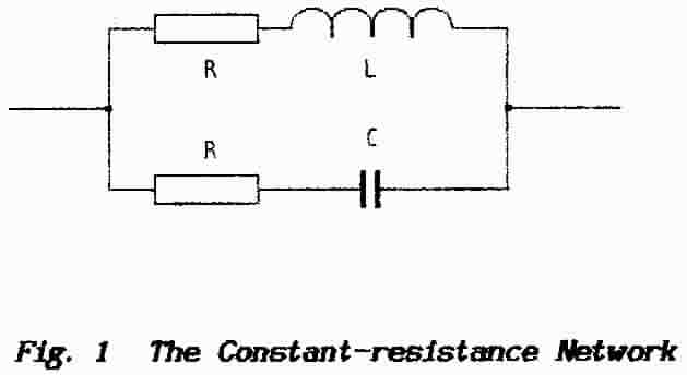
A normal practical parallel-combination of Inductor and Capacitor would be shown with a resistor in series with the Inductive branch only and this represents the resistance of the wire with which the component is wound plus a small amount extra to account for losses inherent chiefly in the core material. Losses associated with capacitors are small when compared with those of an inductor and usually would be ignored. To make a constant-resistance network the resistance (losses) in both branches of the circuit are equalised.
The resistance in the inductive branch is usually designated RL and that in the capacitive branch RC; to make a Constant-resistance Network the criteria are:
RL = RC
L / C = R2
(The mathematical derivation of this relation is given at the end of this Information Sheet. Those familiar with network theory might recognise this as a critically-damped resonant circuit.)
The arrangement is useful, for example, when designed into the output circuits of Signal Generators; given that the apparent “internal impedance" (the source impedance) of a generator has the nature of a resistor it is possible to give a single specification for the output signal which covers the full frequency-range of the instrument.
Another use for this circuit is to suppress the arcing that occurs when a switch breaks an inductive circuit. It does seem to be known that a combination of resistor and capacitor connected across the switch-contacts makes a better suppressor than a simple capacitor but few seem to know why or how to select the value of the resistor; even less seem to know how to use the constant-R network.
Inductance in an electric circuit has the same nature as a flywheel in a mechanical device; i.e. it tends to resist change. When an electric circuit is interrupted inductance tends to keep the current flowing but, because of the interruption, such a current has nowhere to flow. As with transmission-line and aerial theory the effect is to pile-up electrons on one side of the switch and to remove them from the other.
The resulting voltage which is generated across the circuit-break is referred to as an “inductive kick” or usually as the back-emf of the inductor. At the moment that the break is created there is only a small separation between the switch contacts and the resulting “voltage gradient” can be sufficient to ionise the air within that gap; these ions support the continuation of current-flow.
Such “arcs” however tend to be struck over small patches of the switch contacts which causes localised heating with further ionisation as the contact material melts and so the arc is sustained as the contacts move further apart.
Sometimes the circuit which is broken contains significant inductance (e.g. an electric motor) but, in any event, it contains stray inductance distributed along the length of various conducting paths. In combination with stray capacitances these form resonant circuits. When the switch is opened such resonant circuits are left undamped and they oscillate freely at their natural resonance frequencies; as a result, whether the power-supply is ac or dc, the arc is sustained by an alternating voltage. The resulting rf alternating currents are the cause of radio-interference.
The cure is to ascertain the value of the circuit-inductance and the associated resistance and then to add in parallel a capacitor-resistor combination that satisfies the above equation. When this is correctly achieved an arc is not generated (or is greatly reduced) because effectively the switch is breaking a resistive circuit.
Fig. 2 shows the different arrangements. In diagram (a) the switch contacts are shunted with a resistor-capacitor combination. The idea is that the capacitor allows passage to rf but does not restore the dc-continuity that was broken by the switch action. The energy of the alternating currents is dissipated as heat in the resistor.
In diagram (b) a resistor-capacitor combination has been connected, not across the switch, but across the load and the values have been chosen to satisfy the relation L / C = R2. When the correct component values are used rf current does not flow.
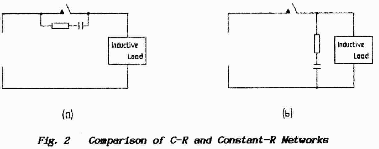
However, Fig. 2 is more than just a comparison of two alternative methods. Should the power-supply and its connecting wiring be bypassed with a low-inductance capacitor (immediately to the left of the switch shown) then diagrams (a) & (b) are seen to be identical. Apart from being food for thought this gives a clue as to the choice of values for C & R in diagram (a).
A practical example of the application of this network is given at the end of this Information Sheet .
These two combinations are connected in parallel and so their effective impedance is found using the “product-over-sum" rule:Let the inductive branch of the network be represented by RL + jXL
Let the capacitive branch of the network be represented by RC - jXC
Z = (RL + jXL)(RC - jXC) / (RL + jXL + RC - jXC )
which simplifies toZ = (RL + jXL)(RC - jXC) / (RL + RC + j(XL - XC))
The result of evaluating this equation has to be the production of resistive terms plus other terms which are reactive (they contain j ). For the network to be aperiodic (non-resonant) the reactive terms must not be present (i.e. they must sum to zero) thus leaving only a resistive component. Thus the task is to manipulate this expression into the general form (a + jb) and then equate the j-terms ( “b” ) to zero which (hopefully) will yield the required conditions.
I do not propose to develop the entire argument here. The masochists among you will enjoy the algebra; the rest will not read it. Hence I give only guidelines.
To be able to separate the top line into R and jX components the bottom line must be reduced to a form without j-terms. This is done using the algebraic relation that a2 - b2 = (a + b)(a - b); i.e. the expression is multiplied by 1 in the form of
RL + RC - j(XL - XC))/(RL + RC -j(XL - XC))
This operation converts the j-terms on the bottom line to j2-terms; because j2 = -1 the bottom line is no longer frequency conscious and so the top line can be separated into resistive and reactive terms each divided by the bottom line.
However, it is only the reactive terms which are of interest and so it is not necessary to multiply-out the horrible-looking expression that has resulted. Concentrate only on those multiplications in the top line which result in reactive terms.
When further simplification is no longer possible put RL = RC = R and the j-terms should be revealed as
j(R2 - L /C)(XL - XC)
For the network to be aperiodic these terms in j must sum to zero and so(R2 - L/C)(XL - XC) = 0
For this to be so either (XL - XC) = 0 ... (resonance) or R2 - L/C = 0whence R2 = L/C
8.10.4 PRACTICAL EXAMPLE
A small dc motor was used which had been recovered from a defunct video- recorder; it operated from 7.5 volts. In place of a switch one of the connecting wires was rubbed against a metal terminal which produced a barrage of crackles as heard on a f.m. receiver tuned to approximately 100-MHz ( the receiver was not tuned to any broadcast signal).
The first task is to measure the resistance and the inductance of the motor. The first measurement involves the straightforward application of a multimeter and it was found to be 8.5 ohms.
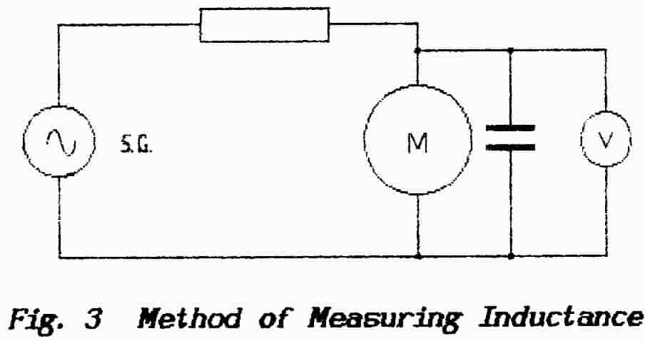
The inductance was measured using the arrangement shown in Fig. 3. The motor was shunted with a 0.47 μF capacitor to resonate it and it was connected to an audio oscillator (a Tone Source) via a 2.2-kilohm resistor. These components happened to be on the bench! An alternating voltmeter was connected across the motor. Variation of the signal-generator frequency produced a maximum response on the voltmeter at 2.340 kHz.
The inductance of the motor can be calculated from the formula for resonance-frequency f = l/(2π√LC)
Hence
2.340 = 1/6√{(L x 0.5 x l0-6)} approx.
= l03 / 6 x 0.775√L approx.
and so√L = 103 / (4.65 x 2.340) = 103 / 10.88 x 10⁻³
L = (1/11)2 = 1000/121 millihenrys
OR 8.5 mH approx
The capacitor required for correction is given by
L/C = R2 or C = L/R2
whence C = 8.5 x 10⁻³ / (8.5)2 = 10-3/8.5 F = 1000 / 8.5 μF
= 118 μF approx.
The standard-value components of 100 μF and 6.8 ohms effectively removed all interference when connected in either position.
END OF INFORMATION SHEET 10