The technique of applying feedback has become fundamental in Electronics but it is not unique to that discipline; indeed it is an essential part of the Universe itself. It is the heart of any control system; on the broadest possible basis it is the mechanism that decides the difference between order and chaos.
In its treatment feedback can be divided into three separate areas:
At its most simple the technique consists of taking a small sample from the output of a system and feeding it back to the input of that system. The feedback sample of course is mixed with the normal input to the system and this gives rise to two possibilities:
(a) the sample which is fed-back can oppose (tend to cancel or to negate) the action of the normal input signal
(b) the sample which is fed-back can aid the action of the normal input signal.
Feedback of type (a), where that feedback opposes or tends to negate the normal input, is known as negative feedback (n.f.b.). Feedback of type (b), where the feedback aids the normal input, is known as positive feedback (p.f.b.).
Before delving into the intricacies of electronic feedback it can be instructive to study the technique in a simple well-known domestic system namely a pan of water which has been set over a heat source.
The temperature of the water rises steadily until it reaches 100°C; at this temperature the liquid phase of water becomes unstable and the liquid becomes gaseous. The heat that is supplied by the heat-source is now utilised in turning the water to steam and so the temperature-rise is checked. The steam is generated at the bottom of the pan where the heat is applied and, in escaping to the Atmosphere, the rising steam-bubbles cause turbulence which we know as boiling.
Such a system is completely uncontrolled; the rate of boiling does indeed depend on the rate at which heat is applied but it depends also on the rate at which the water-pan system can lose heat either to the surrounding air or in the formation of steam. There is little, if any, connection between the manner in which heat is applied and the manner in which heat is lost.
This boiling-pan system can be converted to a controlled system by covering the pan with a weighted lid. Now, when steam is generated, it cannot escape to the atmosphere; further, because steam occupies a greater volume than the water from which it was derived, the pan becomes pressurised.
As pressure within the pan increases so the system must eventually reach a point where the internal pressure can support the weight of the lid; beyond this pressure the lid is lifted from the rim of the pan and steam is allowed to escape. There are now three possible conditions:
(a) at first the gap between lid and pan is small; the quantity of steam which escapes is less than the quantity generated and so pressure continues to rise thus lifting the lid still further from the rim.(b) the gap between lid and pan becomes large; the quantity of steam which escapes is now greater than the quantity generated and so pressure falls thus lowering the lid.
(c) in practice the lid continually rises and falls (thus demonstrating that a normal control system constantly over-corrects (see the end of this Information Sheet) but, theoretically, an exact balance is possible where the lid remains open just sufficiently to allow steam to escape at the rate of generation. Should this condition be attained then the pressure (and also the gap between lid and rim) must remain constant.
These three conditions embody the requirements of a simple n.f.b. system. The Gap between lid and rim can be regarded as the primary Agency (the Cause) which controls the Pressure within the pan; in turn, the Pressure (because it moves the lid) modifies the Gap (the original Cause). Alternatively the Pressure can be regarded as the Cause which, by adjusting the Gap, regulates the Pressure. Such a circular argument, in which Cause and Effect are difficult to separate, is typical of feedback arrangements. It is easy to see why they are named feedback loops.
NOTE THAT, whatever is regarded as the primary Cause, its effect is propagated around the feedback loop eventually to modify that Cause.
With reference to the three conditions listed above:
(a) the gap between lid and rim can be reduced by adding more weights; as a result less steam escapes and the pressure increases. The lid with its extra weight is forced back toward the starting position; i.e. the tendency for the lid to close under the extra weight is resisted. There is only a slight disturbance to the feedback loop but the Pressure is raised.
(b) the gap between lid and rim can be increased by removing weights. As a result more steam escapes and the pressure falls. The lightened lid falls back toward the starting position; i.e. the tendency for the lid to open under the reduced weight is resisted. There is only a slight disturbance to the feedback loop but the Pressure is lowered.
It follows that the addition of a weighted lid to the open pan of water has turned an uncontrolled system into a negative-feedback controlled system that resists any effort to interfere with its steady controlled way of boiling water. One of the most intriguing aspects of feedback systems however is the ease with which a n.f.b. system can be converted to a p.f.b. system (often unintentionally).
For the water-pan this can be achieved by replacing the weighted lid by one which is adjusted by means of an electric motor. The motor is controlled by a sensor within the pan that reports the pressure. A motor which is controlled in this manner by a feedback-loop is termed a servo-motor.
To achieve p.f.b. it is arranged that, when pressure within the water-pan rises, the lid is lowered where previously it was raised; similarly, if the pressure falls, the lid is raised where previously it would have been lowered.
Forcing down the lid when pressure is rising reduces the escape of steam and so causes the pressure to rise still further; provided that the servo motor and its power-supply are capable of exerting the necessary force the result has to be a rapid closure of the lid with disastrous results. The once-safe system has now become unsafe and the once-stable condition quickly becomes chaotic. It goes BANG.
Raising the lid when pressure is falling increases the escape of steam and so lowers the pressure still further; the end result is the uncontrolled system first described above. This last is not an unsafe condition while water remains in the pan but both responses result in loss of control and the chaotic distribution of water.
(Note that, if the connections are re-arranged so that rotation of the motor is the reverse of that described, then the system is once again under n.f.b. control.)
Thus arises the two basic definitions:
(a) n.f.b. is a control system that leads to stability and order
(b) p.f.b. is a control system that leads to instability and chaos.
Surprising though it may seem there are circumstances in which p.f.b. is applied deliberately; e.g. in most switches the abrupt habits of p.f.b. are utilised to speed up a mechanical operation that otherwise would take so long that the switch contacts suffer damage by arcing. It is also an essential part of a maintained oscillator.
Needless to say, when p.f.b. is employed, it is necessary to be careful and a major task for the Designer is to make certain that things will not get out of hand. One of the most powerful tools used in maintaining such control is negative-feedback.
But why go to all this trouble to make a system which might suddenly go berserk? Who would want to boil cabbage under servo control?
The water-pan is a simple arrangement which admirably demonstrates the essentials of a feedback system but, as a practical proposition, it is perhaps a waste of effort? (The pressure cooker utilises a variation of the technique to permit cooking at superheated-steam temperatures. In this device there is a crude form of n.f.b. in which a spring-loaded valve vents steam when the pressure reaches the desired value. Then again the lid is designed with p.f.b. so that internal pressure forces it more tightly against its rubber seal).
In electronic systems the benefits of both kinds of feedback are not only desirable but have become essential. The application of n.f.b. enables a Designer to:
(a) reduce drift caused by temperature changes, power-supply changes and ageing effects
(b) control bandwidth
(c) reduce distortions
(d) control both input-impedance and output-impedance
(e) reduce the effects of manufacturing tolerances thus ensuring that equipment performs to specification both after manufacture end after replacements during repair.
(f) control the effects of p.f.b.
Positive feedback is applied to
(g) speed-up operations which otherwise take too long to complete
(h) deliberately cause instability in the form of (n.f.b-controlled) oscillations
(j) increase the amount of n.f.b. which may be used without incurring risk of instability (this trick is used mainly in valve-operated audio amplifiers).
Except where the object is to produce power, perhaps to drive an electric motor, electronics tends to overlook the fact that electricity always has two parameters namely voltage and current. Although some systems may be voltage driven (e.g. valves) and others current driven (e.g. bipolar transistors) nevertheless the signal is always present in both voltage and current form. It follows that a feedback sample can be derived by tapping either parameter.
The question is perhaps understandable: "Does it matter?" The answer very definitely is “ Yes “.
When the signal is delivered to a purely resistive Load the current and voltage waveforms are identical in form and phase and so, provided the load is not changed, it would appear to make little difference how a feedback signal is derived. For a reactive load however the difference is more obvious.
Remember that the effect of feedback is to stabilise the primary Cause from which the feedback is derived. Thus, when a feedback signal is derived from the voltage waveform, the overall system tends to maintain that voltage waveform irrespective of what may happen to the current waveform. When a feedback signal is derived from the current waveform then the overall system tends to maintain that current waveform irrespective of what may happen to the voltage waveform.
A system that maintains the voltage conditions irrespective of changes in the load (changes in the demand for current ) can be looked upon as offering an internal impedance (a source impedance) which is low with respect to that of the Load... whatever the value of the load-current very little of the generator’s e.m.f. is lost across its internal-impedance and so the terminal voltage remains substantially constant. In contrast, a system which maintains the current conditions irrespective of changes in the load is offering a source impedance which is high with respect to that of the Load... a change in the Load-impedance makes little difference to the overall circuit impedance and so the load-current remains substantially constant.
For example: A valve-operated amplifier is controlled by the voltage which is impressed between its grid and cathode; the two electrodes are insulated form each other and so they form a capacitor. As a consequence the reactance between grid and cathode falls as frequency is increased. The terminal voltage of any generator falls as the current demand increases and so the voltage impressed between grid and cathode must be distorted by a selective loss of high frequencies. This kind of distortion is reduced if the source impedance is relatively low and this can be arranged by use of voltage-derived n.f.b. applied to the previous stage so that the voltage waveform is maintained as the load current varies.
As a contrast the operation of a bipolar transistor is controlled by the current which flows between its emitter and base but the resistive component of this input path depends on the magnitude of the input current. This variable input-resistance leads to distortion of the input current-waveform. Such an amplifier needs to be driven from a stage to which current-derived feedback has been applied thus ensuring that it drives the bipolar stage with a current whose waveform is maintained irrespective of load variations.
In these two examples n.f.b. is being used to control the source impedance; a low output-impedance is necessary to produce constant-voltage drive and a high output-impedance is necessary to produce constant-current drive.
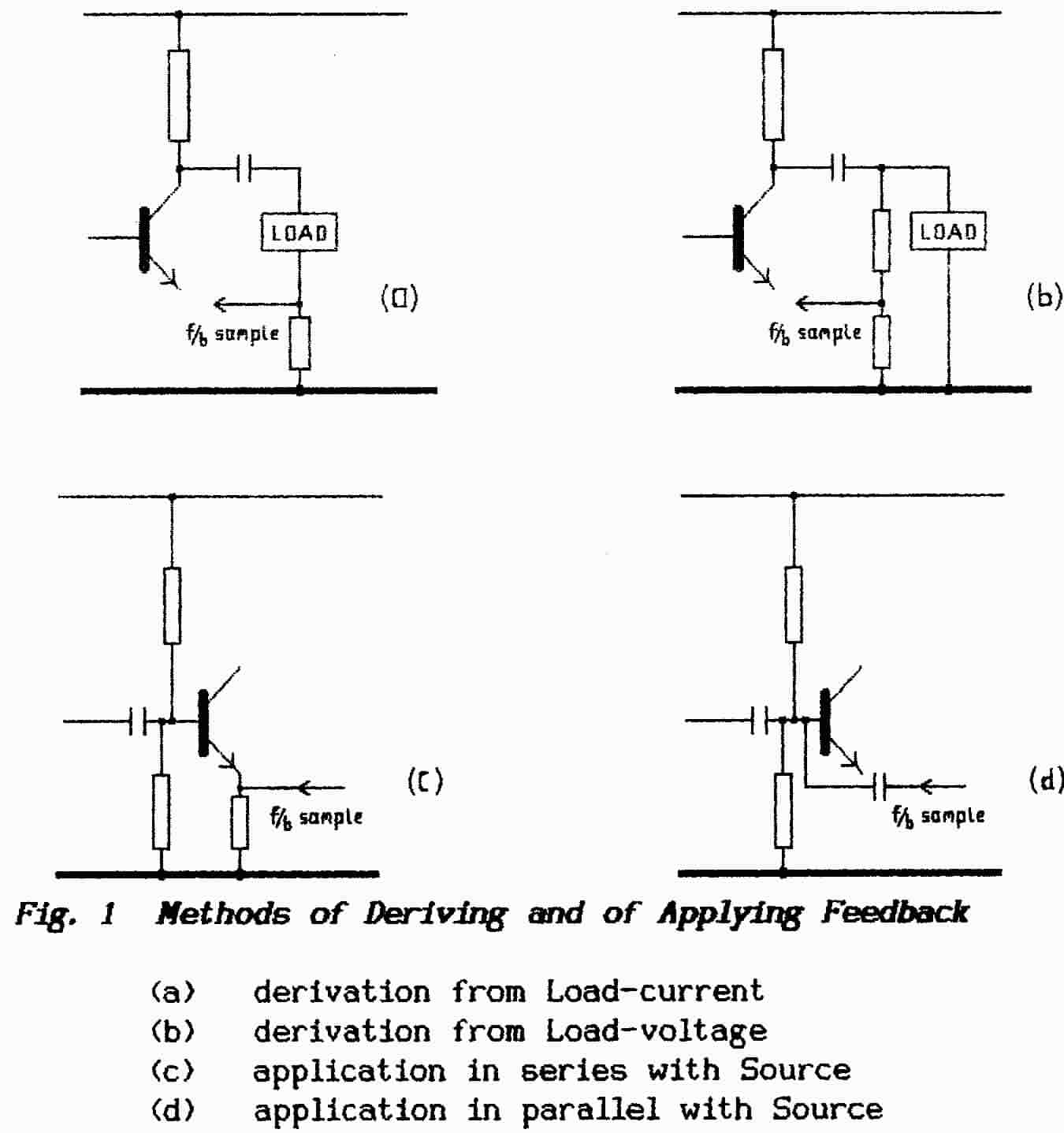
To sample a current-waveform it is necessary to insert a probe in series with a circuit as shown in Fig. 1(a); to sample the voltage waveform all that is necessary is to make a connection across the circuit as in Fig. 1(b). When applying the feedback-signal at the input to a system there is a similar choice in that the feedback sample can be applied either in series with the input signal as in Fig. 1 (c) or in parallel as in Fig. 1 (d).
When the connection is made in series with the input source then both input source and feedback circuit share a common current but they may add or subtract their voltages. It is to be expected therefore that series connection of a feedback signal results in a change of the overall voltage applied between base and emitter of the transistor without changing the input current. Thus, to preserve the output at the level it would have without the application of feedback, it is necessary to raise the overall input voltage (the drive signal) between input and ground. Such an increased input without change in the input current means that the input impedance has apparently been increased.
When the connection is made in parallel then both the input source and the feedback circuit share a common voltage but they may either add or subtract their currents. It is to be expected therefore that a parallel connection of n.f.b. will result in a reduction of the input current to the transistor; when the input signal is driving current into the base so the feedback circuit wants to suck-out current.
Once again, to preserve the output at the level it would attain without feedback, it becomes necessary to increase the overall current-drive between base and ground; this corresponds to an apparent decrease in the input impedance.
A proper grasp of the two methods for deriving feedback signals and of the two methods of applying them is essential for anyone who undertakes design work but it is important too for those seeking to diagnose, trace and repair faults. For example, investigation of the (mis)behaviour of a circuit with the aid of a standard voltage-driven oscilloscope may yield some very puzzling waveforms should the oscilloscope be attached to a point within a current-loop.
The answer is to introduce a small series-resistor and connect the oscilloscope across that; if the circuit is maintaining the current waveform come what may then such an addition (with reasonable care) will not upset the applecart (The ‘scope must not have an earthed input circuit else it will disturb the dc conditions!).
Fig.2 shows a simple n.f.b. circuit which is much misunderstood but which demonstrates many of the effects of feedback . When the emitter by-pass capacitor is omitted a signal voltage is developed across the emitter resistor; although both input and output currents flow through this resistor this is mainly a copy of the (much larger) current which flows in the output circuit.
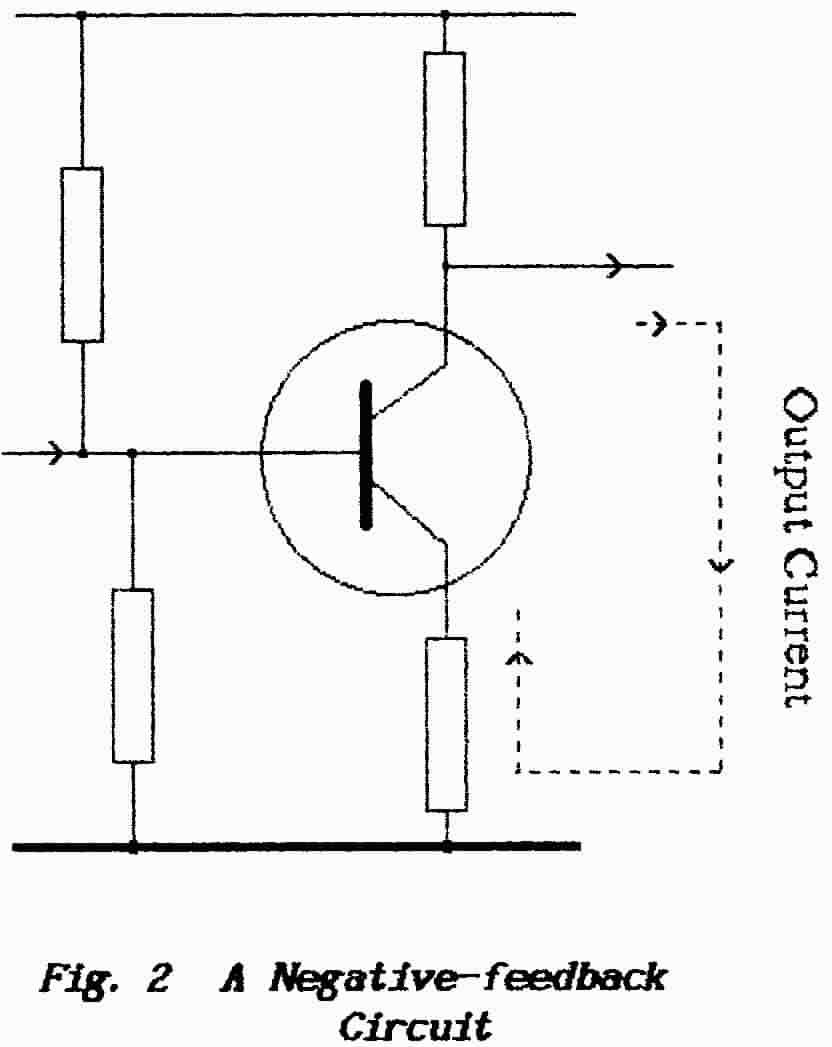 |
In turn this voltage is applied between base and emitter of the amplifier in series with the driving source. The circuit therefore provides current-derived series-applied n.f.b. which results in a high output- impedance and low input-impedance. The high output-impedance is as required if the following stage is a bipolar transistor but would be a disaster if the load is a loudspeaker. The behaviour of a loudspeaker in this circuit can be very complex. To begin, the application of current-derived n.f.b. means that the speaker is supplied with a constant-current; a speaker is an inductive device - its impedance rises with increasing frequency and there is also a continuing change of phase between applied voltage and the current which flows. The power dissipated by the speaker is given by I2Z and so, as the speaker impedance rises with frequency, so too does its power dissipation. Thus the sound from the speaker is enhanced at the higher frequencies and it appears to screech. |
Loudspeakers show a mechanical resonance at low frequencies (usually between 30 and 300 Hz) and, at these points, their electrical impedance rises steeply . Given a constant-voltage drive they suffer a fall in input power (E2/Z) at the resonance frequency and this has the apparent effect of damping that resonance. However when driven from a current source the speaker suffers an increased drive around the resonance frequency and so its mechanical deficiencies are enhanced.
When the feedback signal is derived from a loudspeaker-circuit it is affected also by the continual phase-shift as frequency increases and this may have the unfortunate effect of moving the feedback toward p.f.b. Although instability may not result the overall effect must depend on the driver-circuit. When a circuit is close to oscillation because of phase-shift effects distortion appears first at signal peaks and the unit may be seen on an oscilloscope to burst into oscillation on those peaks with unfortunate effects to the ear.
All things in life demand a price and feedback is not an exception. In electronic circuits the only real drawbacks when n.f.b. is applied lie in the loss of overall gain and the risk of oscillation. Briefly oscillation is prevented by paying attention to phase-shifts within the feedback loop . Reduced gain is overcome by the simple expedient of providing more gain in the chain before n.f.b. is applied. From this arises the two parameters Open-loop Gain and Closed-loop Gain. The difference between these two figures, expressed in decibels, gives the “amount of feedback”.
To test/repair a feedback amplifier does require a modicum of expertise however in that it may be necessary to open the feedback loop. Where the feedback is ac-coupled this may entail no more than a disconnection or a grounding although it may be necessary to provide suitable terminations . With a dc-loop or a combined dc+ac loop it is necessary to take steps to maintain the dc-operating conditions around the loop. Opening a loop (i.e. disconnecting the n.f.b.) obviously causes a rise in the gain from input to output and, with test leads connected, this is an irresistible invitation for the amplifier to oscillate! Truly a substitute for experience does not exist.
A closed-loop servo system demonstrates another failing of n.f.b. in that servo-control is not possible unless it “fails”. Consider a servo-control whose job is to keep an aerial pointing directly toward a transmitter; should the aerial be accurately aligned then the error is zero, the feedback error-signal is zero and so the degree of control also must be zero. Under these conditions the aerial is likely to wander until sufficient error-signal has been generated to activate the servo motor?
The result (termed hunting or sometimes backlash) is that the aerial points more or less at the transmitter but it constantly wobbles back and forth about the true bearing. How far does the aerial wander before the servo-motor cuts-in? This depends on the amount of gain “around the feedback loop” — in other words on the open-loop gain of the servo amplifier. The greater this gain so the smaller is the error but, once again, there is a price to be paid.
A very-high gain implies that the motor is brought into operation for very-small errors and so a “tight” control is maintained. Now suppose that a gust of wind deflects the aerial; the error-sensor sounds the alarm and the servo-motor generates a torque to correct the aerial position. However, if the gust is of short duration and the servo-system takes a comparable time to respond, it could be that the aerial is already returning to the correct position at the moment the motor starts to operate; with the aerial moving in the same direction as the “correcting” motor the system will over-correct and the servo makes matters worse than if it had not operated at all (n.f.b. has turned into p.f.b.).
This sort of situation can be dealt with by using two separate servo loops. The first is a high-gain loop as described above whose job is to keep the aerial pointing on the correct bearing; it is known as a positional servo. The basic problem with the high-gain loop is that it is too keen on doing its job; its obsession with the correct bearing can be curbed by making it slow to operate. This servo-amplifier is designed therefore with a narrow bandwidth and this prevents any fast responses; i.e. it cannot reproduce fast transients.
The second feedback loop is designed to react very quickly - it has a wide bandwidth - but, to prevent over-corrections , it must be more “laid back”; before it does anything it will “wait and see”. This amplifier is designed with lower gain as well as wide bandwidth. The job of this servo-loop is to assess the acceleration of the system and so it is known as a rate servo. Should that gust of wind be short-lived then , although the aerial receives immediate correction from the servo motor, the low-gain delivers a relatively weak push and it fails to produce very much in the way of acceleration. (The slower-acting positional servo is denied time to get off the mark).
Should the gust last for some appreciable time then the aerial will really start to move, the rate-servo detects a rising crisis and generates a correction. NOTE that the rate servo must be able to disable the positional servo else conflict will result. Its greater bandwidth makes it faster in action and so it disables the positional loop before matters get out of hand.
It is interesting to see this in action in our own bodies. The eye is very accurate at estimating position but it responds to light in only the so-called visible range; this is but a fraction of an octave. Hence, in maintaining the upright position, it must serve as a positional servo (it is known to be slow when observing motion). The canals of the inner ear, often described as an organ of balance, are found to respond over approximately 3.5 octaves; this wide bandwidth must mean that it is a rate-servo. It does not tell us that we are falling but how fast we are falling. The necessary over-riding action probably takes place in the Brain. Without knowledge of the rate-of-fall the muscle systems could not apply the correct forces to maintain our upright stance. Such a stance on two legs requires small amounts of position-correction that is fast-acting; for elderly people the overall response-rate falls and their balance becomes precarious.
Back to Top of PageEND OF INFORMATION SHEET 8