Home Page
PART 8: INFORMATION SHEET No. 7
CIRCUIT DIAGRAMS
(Written By Request)
8.7.1 INTRODUCTION
Circuit diagrams are intended as a pictorial
representation of the arrangement and the inter-relation of the various components
which go to make a piece of electronic equipment. They do not represent the
physical layout of the components.
It is possible to describe a circuit in words.
For example:
"Resistor R3 is the collector-load resistor for transistor TR1 and
it is connected between the collector-stopper resistor R4 and the low-potential
end of the stage-decoupling resistor R2". This may be comprehensible
as it stands but few could make much of a similar description of a four-stage
amplifier with voltage-derived-negative-feedback from a transformerless output
stage which is parallel-applied to the input?
If circuit diagrams are intended to clarify
the construction and operation of equipment then, as with the written word,
it is important that the information can be easily recovered by another person
who is distant in both time and place. To this end it is necessary to adhere
to certain agreed methods of presentation.
Equally it is important that finished diagrams
be clearly labeled and that their titles make it possible to file them in some
system from which they can be retrieved given either a Title (a number) or
a reference such as to the name of the system of which they form a part. I
have met a system in which it was very easy to assign a reference number for
any drawing and yet, once filed, it was impossible to find that drawing again
unless that exact number was known!
8.7.2 BASIC LAYOUT OF A DRAWING
Drawings are laid out using the same conventions
as used in western writing namely the information-flow moves from left to right
across the paper and from the top downward . Of necessity this Rule cannot
be applied rigidly but there are accepted conventions for dealing with difficulties;
see Fig.1.
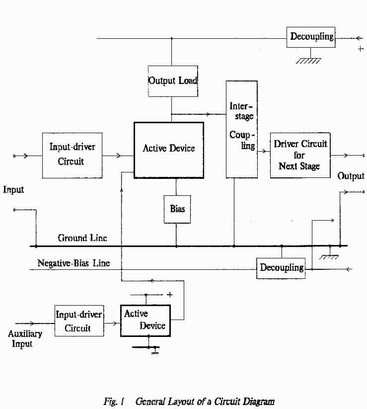
- Signal inputs are entered from the left-hand-side of the paper; signal
outputs are taken to the right-hand-side of the paper.
DC Power-supplies are entered from the right-hand side of the paper; this
often includes the transformer/rectifier circuit from which supplies may
be obtained.
- Where the signal-chain is too long to be accommodated across the paper
then a second line is commenced and this second line too starts at the left-hand-side.
(Drawings are made where in fact the signal-flow is taken from right to
left along the second line; sometimes this may be done for a valid reason
but it should be avoided if at all possible because it will confuse a would-be
reader confronted with a very complex drawing).
- Auxiliary circuits (for example Local Oscillators in a Receiver or an alternative
input amplifier) are drawn immediately below the main-path circuit-arrangement
on which they operate.
( In a two-line main-path the main circuit is drawn on lines 1 & 3 while
the auxiliaries are placed on lines 2 & 4).
- (a) Ground (Earth, earthy, 0-volt) lines are drawn at the bottom of the
main-path using a heavy line
(b) Positive supply-lines are drawn above the circuit except where the major
feed is negative as when using pnp transistors. The higher voltage supplies.are
drawn in the higher positions
(c) Bias-lines (including a.g.c. lines) of either polarity are brought
in below the ground line. Negative supply-lines (in dual-supply circuits)
are brought in below all other lines. Higher-value negative supplies are
drawn in the lower positions.
- In complex diagrams, which make several signal-lines across the paper,
it may clarify a drawing if these supply lines are drawn separately for each
signal line but each must be clearly labeled; where multiple supplies
are used at the same voltage they must be distinguished; for example +12(1)
and +12(2) .(The reference number might be that of the connector-pin through
which the supply enters the unit.
- (a) Input-handling circuits are drawn to the left of the active-device
which they are driving.
(b) Output circuits are drawn above the active-device which is driving them. This
leaves room for any input arrangement, that may be needed to drive the next
Stage, to be drawn to the left of that Stage.
Fixed biases which are derived elsewhere, including such things as a.g.c.
lines , are brought in below the Ground line and up beneath the active device(s)
which they serve.
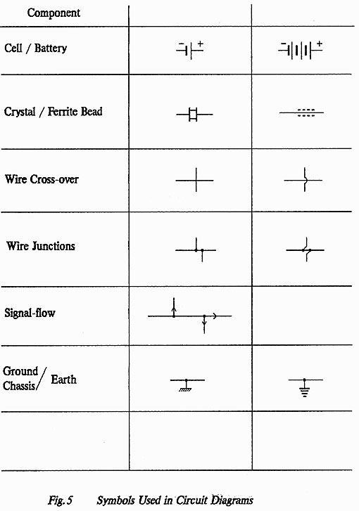
- Connections are always indicated by a dot at the point of connection; crossed
connections are avoided. Where wires cross but do
not make electrical contact they are shown without a dot.
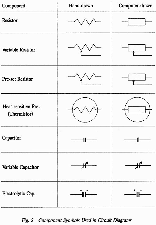
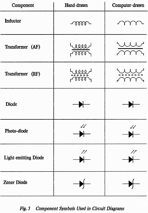
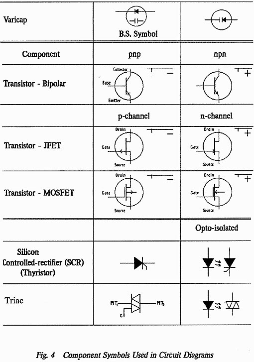
- Standard symbols are used to represent various components (see Figs.
2 to 5); many of these have
been changed to suit computer drawing. For example the old zigzag resistor
is difficult to draw by computer although that is probably not so with
today's graphics packages in which pre-drawn symbols can be picked and
placed with a
"mouse"; note however that the zigzag form is easier
to draw by hand.
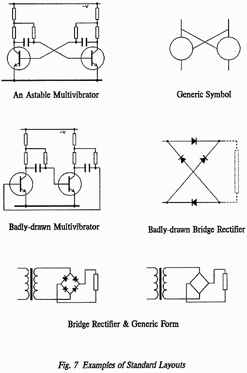
- There are certain standard layouts for particular types of circuits and
these should always be used . Examples are given in the sheets of drawings
attached (see Fig. 7); e.g. a bridge circuit, a
multivibrator. Correct use of these forms makes a circuit-arrangement
immediately recognisable even to the extent of using an abbreviated form
in block-diagrams.
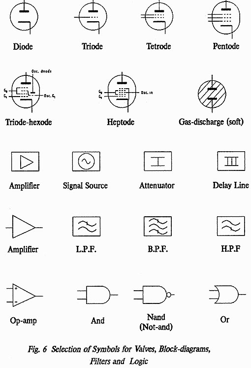
- Standard forms are laid down too for block-diagram use. In general
such diagrams represent each circuit-arrangement as a box within which is
drawn either a standardised symbol or a word description.
- The addition of signal-flow direction-arrows can make both circuit diagrams
and block diagrams much easier to follow but these must be added with care
. Arrows added unnecessarily merely clutter a diagram; they
are most useful when added after a Junction. Do not
use arrows to indicate direct-current flows except of course where dc is
the required signal.
- It is accepted practice to omit dc connections to op-amp and logic symbols.
8.7.3 SYMBOLS USED IN CIRCUIT DRAWING
On the following pages Figs. 2 to 5 show
a selection of symbols commonly used in drawing circuit diagrams although variations
on these will be found. Note that the circles which represent valve/transistor/diode
envelopes are often omitted; much depends on the complexity and
density of a drawing whether these envelopes are best omitted or included.
Fig. 7 shows examples of
standard circuit layouts and one example of a foolish manner in which a multivibrator
is sometimes drawn. Such standard layouts often make it possible to decipher
a complex drawing in a matter of seconds; a badly-drawn diagram
may need to be re-worked several times before even an experienced engineer
can determine its purpose.
Always avoid "tram-lines" - the system
of drawing in which all connections are run in parallel tracks along one (or
more) edges of the drawing. Such diagrams are difficult to read and it is
also very easy to make errors of commission when setting-out and checking the
work. Where some tram-lines are unavoidable then they should be separated into
groups of three or five (max) to enable the eye to follow a particular line
without finger aid.
Back to Top of Page
END OF INFORMATION SHEET 7