Thermistors are variable-resistors whose value depends on temperature. There are two basic types:
(a) Positive Temperature Coefficient (PTC) in which the resistance rises as the temperature is increased
(b) Negative Temperature Coefficient (NTC) in which the resistance falls as the temperature is increased.
PTC thermistors are characterised by low and relatively-constant resistance at low temperatures. As the temperature is increased so resistance increases slowly at first but the rate-of-rise soon increases. When resistance is plotted against temperature the resulting graph shows an abrupt bend or knee which indicates that the thermistor rapidly switches between low resistance and high resistance over a short range of temperature change. This temperature is known as the Reference Threshold, Critical or Switching Temperature.
These devices are used mainly in temperature-sensing arrangements to protect against damage from too-high temperatures or too-high currents (which will produce high temperatures). In general they are connected in series with the circuit to be protected and, at the critical temperature, the increase in their resistance-value limits the current. Their action is that of a heat-operated switch.
They are manufactured in a variety of forms in which is specified their resistance at the critical temperature. Also specified is their resistance a few degrees either side of the critical temperature (showing the rate of change). Their cool/cold resistance and also their maximum power dissipation.
NTC thermistors are characterised by a resistance/temperature curve which is substantially linear (a straight line) over a fairly wide range of temperatures. Different NTC thermistors are matched in manufacture so that they provide overlapping linear ranges which cover temperatures roughly from -80°C to +150°C. Sets of such are known as Curve-matched thermistors.
NTC types are used mainly in temperature measurement circuits where their steadily-decreasing resistance is equated to steadily-rising temperature. They can be used simply as thermometers but more generally in a sensing arrangement that controls the heat-input to a system. Some physically-small thermistors, able both to heat and to cool rapidly, are employed in arrangements in which they provide the feedback signal for a gain-control loop in applications such as oscillators.
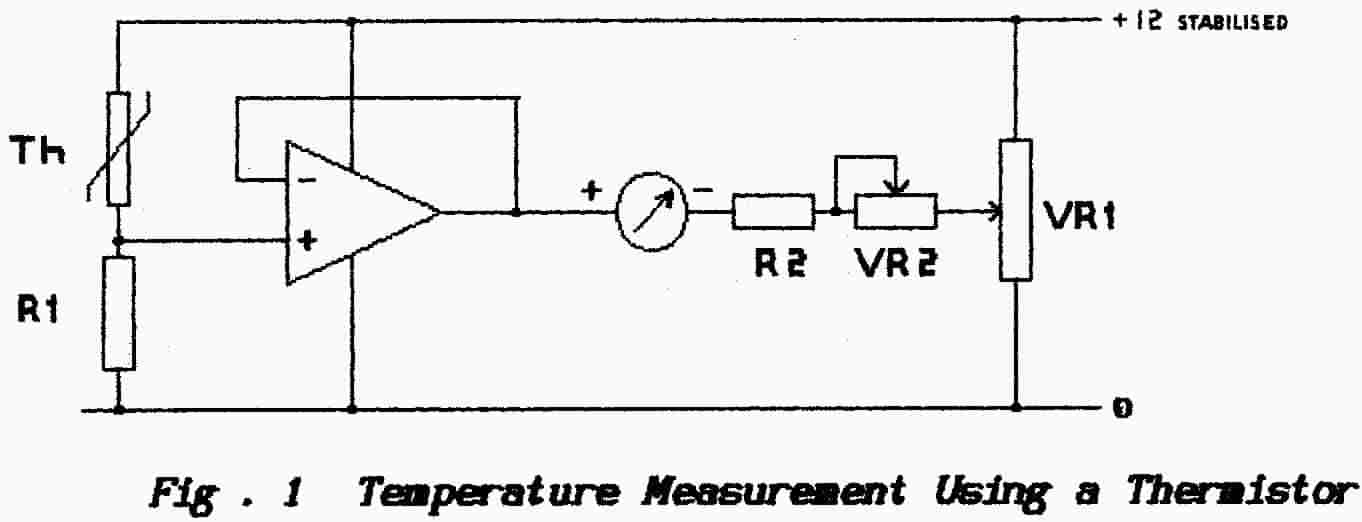
Fig. 1 shows a simple circuit in which a thermistor is used to construct a thermometer. The op-amp, with its output tied to the inverting-input, is being used as a follower (compare with the emitter-follower or cathode-follower circuits) and it acts as a buffer to isolate the sensing circuit from the meter circuit which follows.
As the temperature of the NTC thermistor rises so its resistance falls and the non-inverting input is carried toward the positive supply line. By definition the output terminal of the op-amp follows the non-inverting input and so the positive-terminal of the meter is carried toward the positive supply-line also, this increases the meter-deflection. The pot’meter VR1, connected across the supply, is adjusted to bring both terminals of the meter to the same value at zero temperature; i.e. it is the "Set Zero” control at 0°. The variable resistor VR2 is used to set the full-scale deflection (f.s.d.) when the temperature is at the appropriate value.To measure negative temperatures there are two options:
1. Reverse the meter connections
2. Interchange the positions of the thermistor and resistor R1. This action almost certainly would require a new-value resistor to be switched in place of R1.
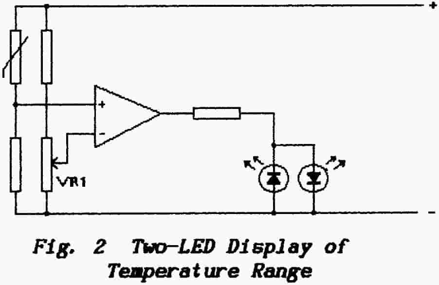 |
Fig. 2 shows a circuit which indicates that the temperature of the thermistor is within a given range. One of the light-emitting diodes (LED) is illuminated when the transistor draws too much current and the other when the transistor draws too little current |
The variable resistor VR1 is used to set the “trip point” but there will be a range of temperatures on either side of this point in which both LED’s will remain dark. To control this range attention must be given to the tolerances involved in the characteristics of both the transistor and the LED’s. A smaller range for the indicated trip-point can be achieved by using an op-amp in place of the transistor.
Alternatively the LED’s may be replaced by a relay (or Triac) which can be used to turn-on the supply to a heater when the temperature falls below the selected threshold or to turn-off that supply when the temperature becomes too high.
The I/V characteristics of thermistors can be modified by adding a resistor in parallel with the thermistor. To increase the current-carrying capacity of a thermistor two or more devices may be connected in parallel.
Back to Top of PageEND OF INFORMATION SHEET 5